Locking Assembly and Dispensing Cartridge Comprising the Same

Inactive Publication Date: 2008-07-24
3M ESPE
View PDF30 Cites 9 Cited by
  • Summary
  • Abstract
  • Description
  • Claims
  • Application Information

AI Technical Summary

Benefits of technology

[0043]According to the present invention, the locking assembly, i.e. the combination of locking assembly and handle, is such that it closes automatically when released and thus locks the tip onto the dispensing cartridge. In case a knee joint is used, for example, high forces are provided which compensate for friction or wear or provide a reliable sealing of the connections on the last millimetres of movement. For disengagement, the handle has to be pressed down at its front end so that it gives way. As described above, there are preferably two steps of release. First, the tip is released. With slightly additional pressure, the handle gives even more way to also release the container, i.e., the foil bag/cap. This results in a substantially easier handling of the dispensing cartridge.
[0044]The dispensing cartridge of the present invention is advantage

Problems solved by technology

This may be uncomfortable.
This, however, increases the risk that the hinge is damaged or that the lever 8 even breaks at the hinge owing to the long lever arm of the force applied by the user at the f

Method used


Image

  • Locking Assembly and Dispensing Cartridge Comprising the Same
  • Locking Assembly and Dispensing Cartridge Comprising the Same
  • Locking Assembly and Dispensing Cartridge Comprising the Same

Examples


Embodiment Construction

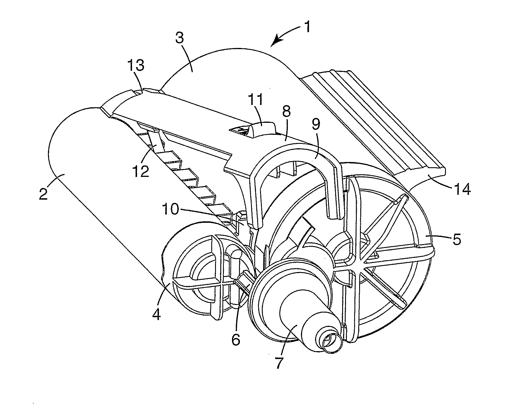
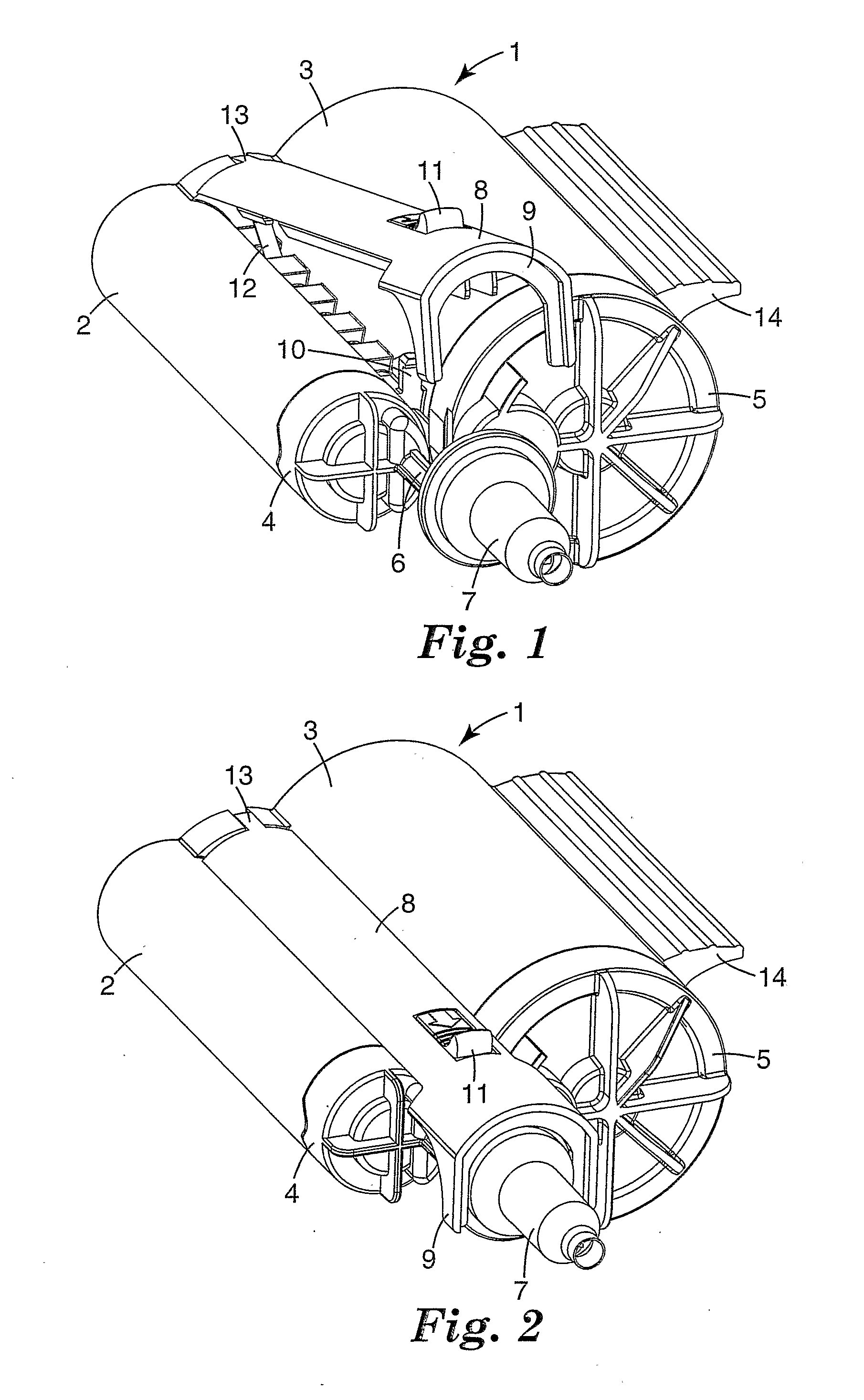
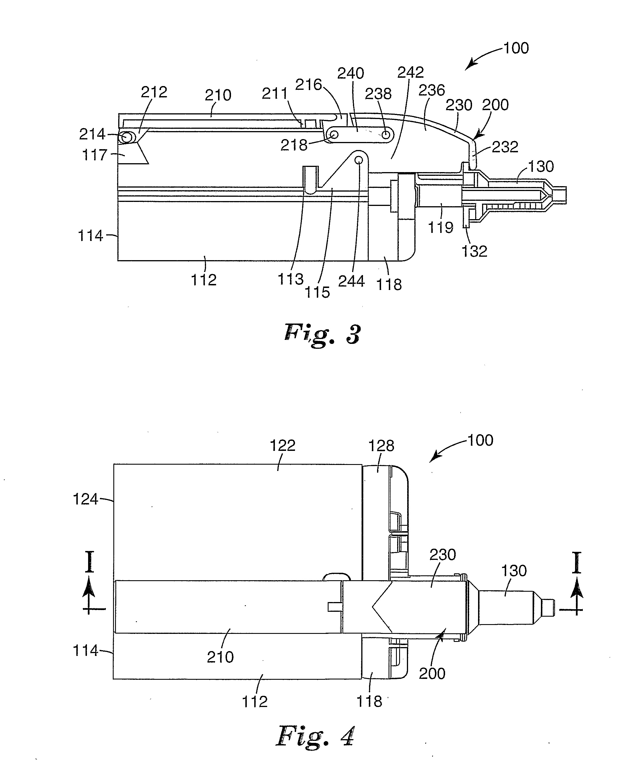
[0059]An example of a dispensing cartridge constructed in accordance with the principles of the present invention is illustrated in FIGS. 3 to 8 and is broadly designated by reference numeral 100. The cartridge 100 according to this preferred embodiment comprises a first compartment with a body 112. Specifically, the body 112 includes a rear open end 114 and a front outlet opening 116 that is remote from the open end 114. The compartment is elongated and extends from the rear open end 114 to the outlet opening 116.

[0060]The dispensing cartridge as shown in the Figures comprises a second compartment having a body 122. The body 122 includes a rear open end 124 and a front outlet opening 126 that is remote from the open end 124. The second compartment is elongated and extends from the open end 124 to the outlet opening 126.

[0061]In the shown preferred embodiment, the dispensing cartridge 100 comprises a locking assembly 200. As can be taken from all FIGS. 3-8, the locking assembly 200 ...


PUM


Abstract

Dispensing cartridge, particularly for dental impression materials, the dispensing cartridge comprising: at least one compartment; and a locking assembly for releasably locking a tip with at least one of the compartments; the locking assembly comprising: a first movable member comprising a first end; a second movable member comprising a first end and a second end, where the second end of the second movable member is adapted to releasably lock the tip.

Description

BACKGROUND OF THE INVENTION[0001]1. Technical Field[0002]The present invention relates to a dispensing cartridge, particularly for dental impression materials, of the type adapted to be releasably received in an applicator having a moveable plunger.[0003]2. Description of the Related Art[0004]A number of dispensing devices are available for dispensing various types of materials. In many instances, the dispensing device is an assembly that includes a reusable dispenser or applicator and a disposable cartridge. The cartridge contains a quantity of a composition or material to be dispensed and is releasably received in a receptacle of the applicator.[0005]In one type of dispensing devices, that include an applicator and a cartridge, the applicator has a plunger that is advanced by the user during a dispensing operation. Often, the plunger is received in an open end of the cartridge and bears against a piston within the cartridge. As the plunger is advanced to move the piston, the pisto...

Claims


Application Information

Patent Timeline
IPC IPC(8): B67D5/52A61C5/06B67D7/70A61C5/62A61C5/64A61C9/00B05B15/06B05C17/005
CPCA61C5/062A61C5/064B05C17/00553B05C17/00506A61C9/0026A61C5/62A61C5/64B05C17/00596
Inventor MULLER-PAUL, DIRK
Owner 3M ESPE
Why Eureka
Try Eureka