Fixing device and image forming apparatus including the fixing device

a fixing device and image forming technology, applied in the direction of electrographic process apparatus, instruments, optics, etc., can solve the problems of poor fixing of toner image onto recording medium, limited reduction in warm-up time, and inability to ignore the problem

Active Publication Date: 2008-07-24
RICOH KK
View PDF15 Cites 101 Cited by
  • Summary
  • Abstract
  • Description
  • Claims
  • Application Information

AI Technical Summary

Benefits of technology

[0017]Described herein is a novel charging device that includes a heat source, an endless, flexible fixing member to fix a toner image by heating and melting the toner image onto a recording medium, a pressure member to press against the fixing member, a stationary facing member to face an inner surface of the fixin

Problems solved by technology

However, there is a limit to reduction in a warm-up time, i.e., the time required for the temperature to rise to a level that enables printing, and a first print time, i.e., the time from receiving a print request to outputting printed paper.
However, it is not the entire fixing film but only the nip portion thereof that is sufficiently heated.
As a result, the fixing film is most cooled down at the entrance of the nip portion due to the rotation of the fixing film, which easily leads to poor fixing of the toner image onto the recording medium.
This problem is not ignorable and is particularly acute with high-speed operation, since the amount of heat dissipated from the fixing film increases everywhere except at the nip portion as the rotation speed thereof increases.
In particular, since the pipe-shaped metal heat conductor is made thin to improve the efficiency of heating the fixing member, the probability of occurrence of the bending problem increases.
When the meta

Method used


Image

  • Fixing device and image forming apparatus including the fixing device
  • Fixing device and image forming apparatus including the fixing device
  • Fixing device and image forming apparatus including the fixing device

Examples


first embodiment

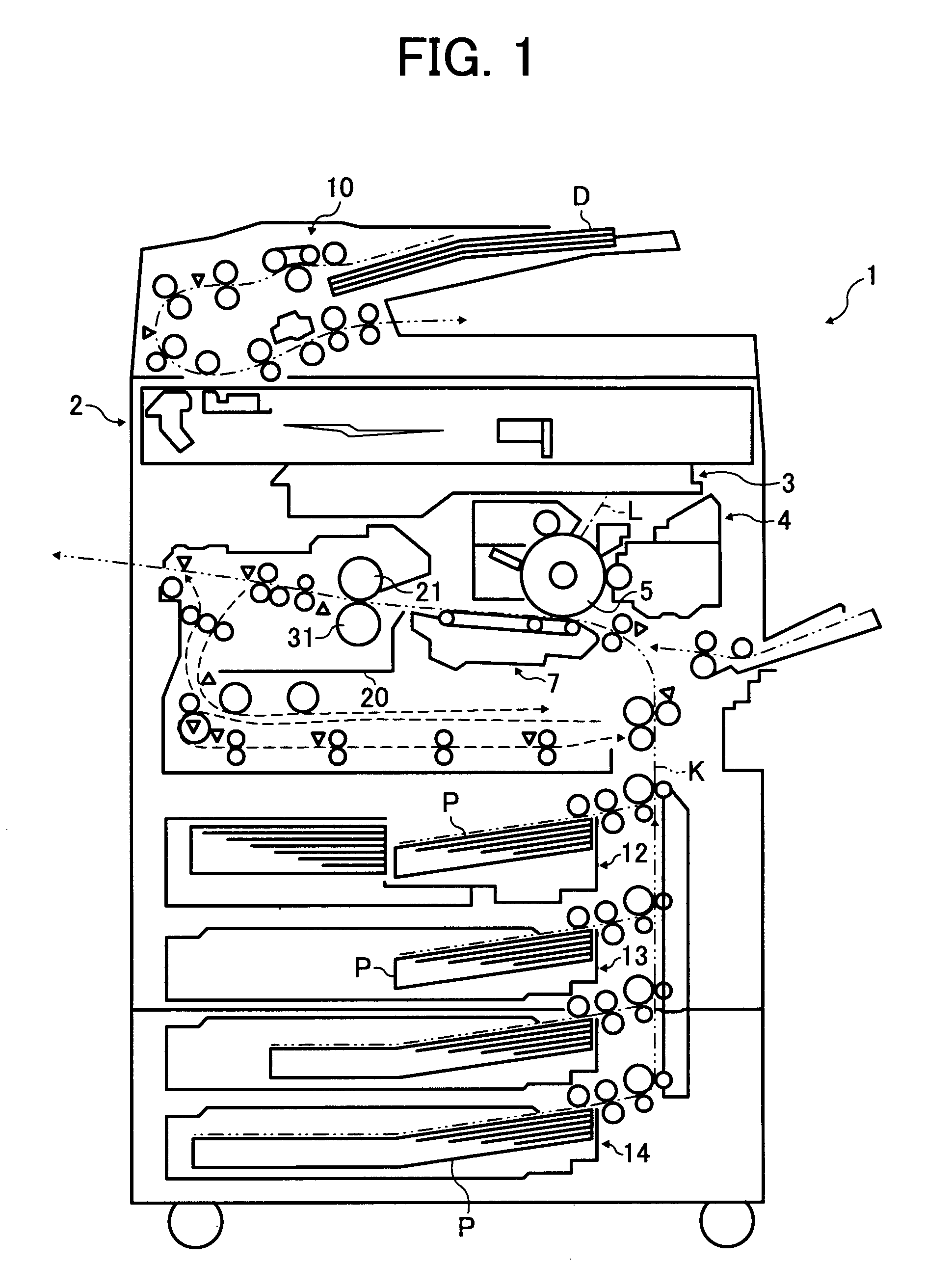
[0032]Referring to FIGS. 1 through 4, the present invention is described.

[0033]In order to facilitate an understanding and appreciation of the novel features and advantages of the present invention, the overall configuration and operation of an image forming apparatus according to the first embodiment are now described, again with reference to FIG. 1.

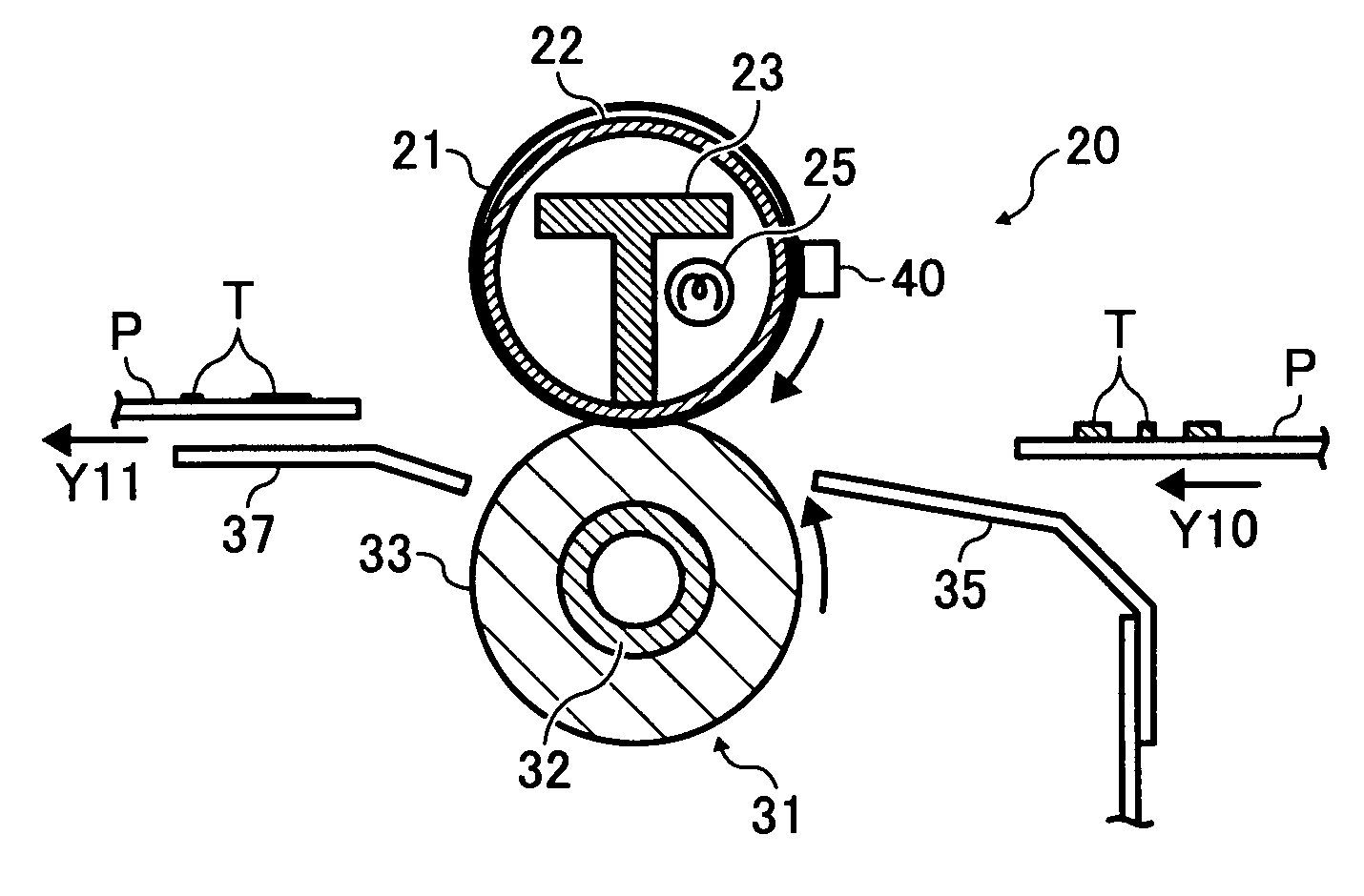
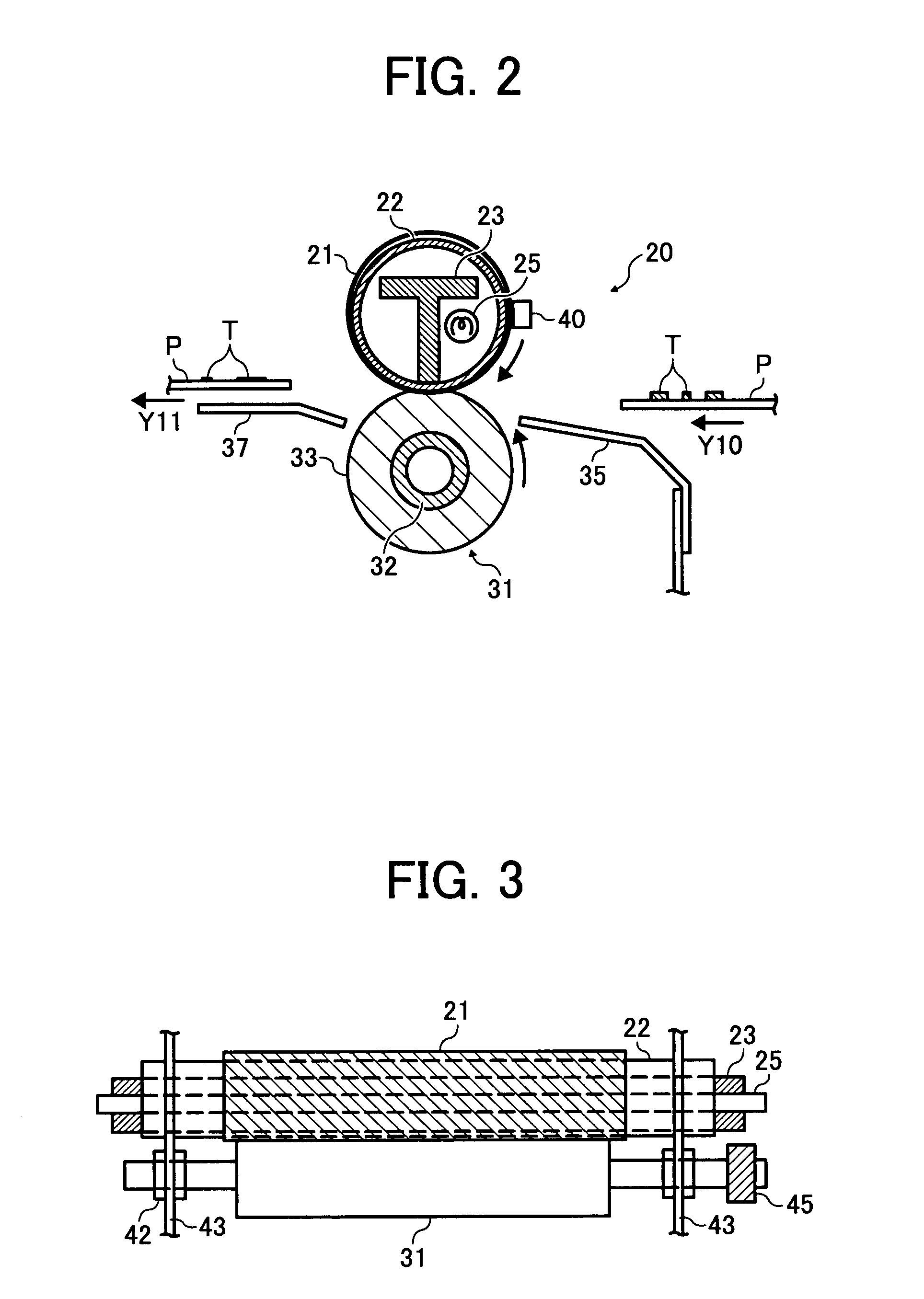
[0034]In FIG. 1, an image forming apparatus 1 includes an original read unit 2 that optically reads image information of an original D, an irradiation unit 3 that irradiates a photoconductive drum 5 with light L based on the image information read by the original read unit 2, an image forming unit 4 that forms a toner image T on the photoconductive drum 5, a transfer unit 7 that transfers the toner image T formed on the photoconductive drum 5 to a recording medium P, an original feed unit 10 that feeds the original D to the original read unit 2, paper feed units 12, 13, and 14 that store the recording medium P such as transfer paper, a ...

second embodiment

[0078]the present invention is now described with reference to FIG. 5.

[0079]FIG. 5 is a diagram illustrating the configuration of a fixing device according to the second embodiment of the present invention and corresponds to FIG. 2 illustrating the first embodiment of the present invention. The fixing device according to the second embodiment is the same as in the first embodiment, except that the facing member 22 is formed such that the nip portion is formed into an inwardly concave shape in the fixing member 21 and a heat insulating member 27 is provided between the reinforcement member 23 and the facing member 22.

[0080]Similar to the first embodiment, the fixing device 20 according to the second embodiment includes the fixing belt 21 (fixing member), the facing member 22, the reinforcement member 23, the heaters 25 (heat source), and the pressure roller 31 (pressure member) as illustrated in FIG. 5. In the second embodiment, however, two heaters 25 are provided inside the fixing ...

third embodiment

[0088]the present invention is now described with reference to FIG. 6.

[0089]FIG. 6 is a diagram illustrating the configuration of a fixing device according to the third embodiment of the present invention and corresponds to FIG. 5 illustrating the second embodiment of the present invention. The fixing device according to the third embodiment is the same as in the second embodiment, except that the facing member 22 is heated by electromagnetic induction.

[0090]Similar to the second embodiment, the fixing device 20 according to the third embodiment includes the fixing belt 21 (fixing member), the facing member 22, the reinforcement member 23, the pressure roller 31 (pressure member), and the heat insulating member 27 as illustrated in FIG. 6.

[0091]The fixing device 20 according to the third embodiment includes an electromagnetic heating unit 50 that heats the facing member 22 by electromagnetic induction, which is different from the fixing device according to the second embodiment in w...


PUM


Abstract

A fixing device and an image forming apparatus including the fixing device. The fixing device includes a heat source, an endless, flexible fixing member to fix a toner image by heating and melting the toner image onto a recording medium, a pressure member to press against the fixing member, a stationary facing member to face an inner surface of the fixing member and heat the fixing member while contacting the pressure member via the fixing member at a nip portion formed between the fixing member and the pressure member, and a reinforcement member to reinforce the facing member at the nip portion by contacting an inner surface of the facing member in a fixed manner.

Description

CROSS-REFERENCE TO RELATED APPLICATIONS[0001]This patent specification is based on and claims priority from Japanese Patent Application Nos. 2006-319412, filed on Nov. 28, 2006, and 2007-127628, filed on May 14, 2007 in the Japan Patent Office, the entire contents of each of which are incorporated by reference herein.BACKGROUND[0002]1. Field of the Invention[0003]The present invention relates to a fixing device and an image forming apparatus including the fixing device.[0004]2. Description of the Related Art[0005]In an image forming apparatus such as a copier or a printer, a fixing belt stretched around a plurality of roller members is a known technique for configuring a fixing member.[0006]A fixing device using such a fixing belt includes an endless fixing belt serving as a fixing member, a plurality of roller members that stretch and support the fixing belt, a heater that is provided in one of the plurality of roller members, and a pressure roller serving as a pressure member. The...

Claims


Application Information

Patent Timeline
IPC IPC(8): G03G15/20
CPCG03G15/2053G03G2215/2064G03G2215/2035G03G2215/2016
Inventor SHINSHI, AKIRA
Owner RICOH KK
Why Eureka
Try Eureka