
Apparatus and Method For Manufacturing Security Paper

a technology of security paper and apparatus, applied in the direction of press section, non-fibrous pulp addition, fibreboard, etc., can solve the problem of preventing monitoring (including visual monitoring) of the deposition of security elements, and achieve the effect of drastic reduction

Active Publication Date: 2008-07-31
FEDRIGONI
View PDF21 Cites 4 Cited by
  • Summary
  • Abstract
  • Description
  • Claims
  • Application Information

AI Technical Summary

Benefits of technology

[0015]The aim of the present invention is to provide an apparatus for manufacturing security paper provided with security elements that is capable of eliminating or in any case reducing drastically the drawbacks noted above in the devices currently in use.
[0016]Within this aim, an object of the present invention is to provide an apparatus for manufacturing security paper that can offer high reliability in operation.
[0017]Another object of the invention is to provide a method for manufacturing security paper that allows to obtain a security paper that can be printed easily.
[0018]Another object of the present invention is to provide a method for manufacturing security paper that allows to control precisely and reliably the width, density and region of deposition of the security elements.

Problems solved by technology

As mentioned earlier, spreaders for depositing the security elements must currently be arranged so that they are more or less immersed in the forming box, and this causes drawbacks.
However, this condition prevents monitoring (including visual monitoring) of the deposition of the security elements.
Moreover, any variation in the operating conditions within the forming box (density of the paste, partial vacuum inside the roller, etc) may determine a change in the conditions of deposition of the security elements (such as width of the band, density of the elements) that are difficult to detect in line, both due to the difficulty of accessing the deposition region and due to the fact that the security elements that are inserted often are not easily visible in transmitted light or in reflected light.

Method used


Image

  • Apparatus and Method For Manufacturing Security Paper
  • Apparatus and Method For Manufacturing Security Paper
  • Apparatus and Method For Manufacturing Security Paper

Examples


Embodiment Construction

[0033]In the examples of embodiments that follow, individual characteristics, given in relation to specific examples, may actually be interchanged with other different characteristics that exist in other examples of embodiments.

[0034]Moreover, it is noted that anything found to be already known during the patenting process is understood not to be claimed and to be the subject of a disclaimer.

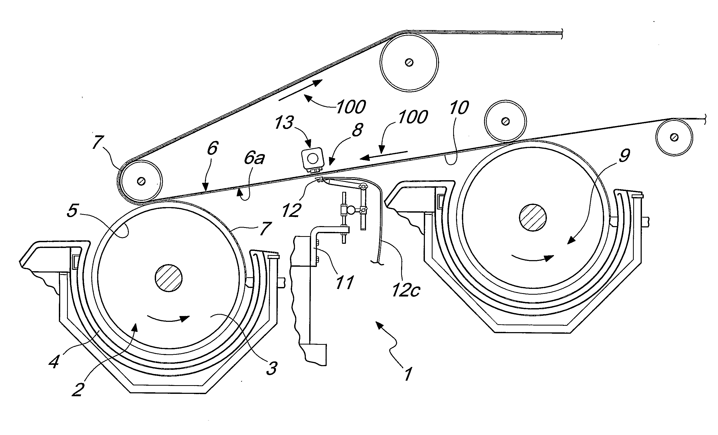
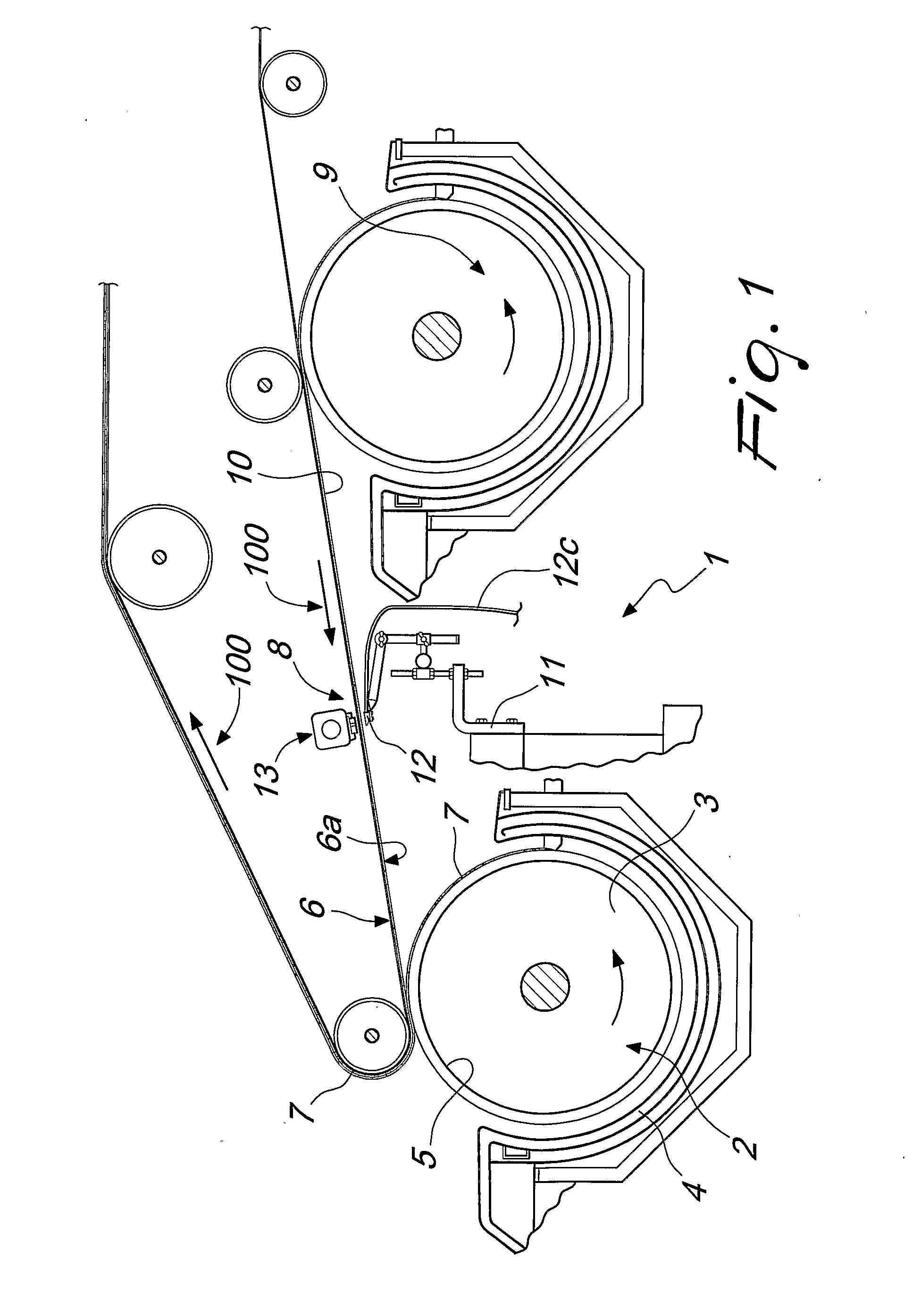
[0035]With reference to the figures, an apparatus for manufacturing security paper 200, generally designated by the reference numeral 1, comprises at least one main forming roller 2, which is provided with a lower or forming portion 3, arranged inside a first forming box 4, which contains the paper paste, and an upper or deposition portion 5, which is arranged below a collecting wire 6.

[0036]In particular, the collecting wire 6 can move along an advancement direction (indicated by the arrow 100) and is designed to receive, at a collecting face 6a, the sheet 7 formed at the outer blanket of the m...


PUM

PropertyMeasurementUnit
Pressureaaaaaaaaaa

Abstract

An apparatus for manufacturing security paper, comprising at least one main forming roller, which is provided with a lower portion or forming portion, which is arranged inside a forming box that contains a paper paste, an upper portion or deposition portion, which is arranged below a collecting wire that can move along an advancement direction and is designed to receive, at a collecting face, the sheet formed on the forming roller, and a device for depositing security elements that is arranged upstream of the main forming roller along the advancement direction of the collecting wire and is adapted to deposit the security elements at the collecting face.

Description

TECHNICAL FIELD[0001]The present invention relates to an apparatus for manufacturing security paper or forgery-resistant paper and to the corresponding method.BACKGROUND ART[0002]It is known that certain types of security papers (used typically to manufacture banknotes, checks, papers for identity documents or passports, etc) are provided with several security devices, which usually include a watermark and / or a security thread.[0003]Some kinds of forgery-resistant papers often have, in addition to the “classic” security devices mentioned above, additional security elements, constituted for example by so-called “plachettes”, fibers, filaments having different shapes, sizes, or granules that can be fluorescent, luminescent, magnetic, magnetizable etc, having various dimensions, sometimes even on the order of 10 micrometers.[0004]These security elements are generally embedded within the sheet (at respective application regions) during its formation, by using feeder devices that are imm...

Claims


Application Information

Patent Timeline
IPC IPC(8): D21H23/24D21F1/00D21F9/04D21F11/00D21H21/40
CPCD21F9/043D21H23/24D21H21/40D21F11/00
Inventor EVANGELISTI, GIANCARLO
Owner FEDRIGONI
Learn More