
Remote diodes in a cordless tool

a technology of diodes and power tools, which is applied in the direction of cooling/ventilation/heating modifications, modifications by conduction heat transfer, printed circuits, etc., can solve the problems of high voltages, battery cells may still be susceptible to charge, and battery cells that cannot discharge, etc., to achieve the effect of reducing the voltage of power electronic devices such as cordless power tools

Inactive Publication Date: 2008-07-31
AGILENT TECH INC +1
View PDF6 Cites 26 Cited by
  • Summary
  • Abstract
  • Description
  • Claims
  • Application Information

AI Technical Summary

Problems solved by technology

Various battery technologies can be damaged when discharged in excess of the manufacturer's recommendations.
As a result, battery cells may still be susceptible to charge, but cannot discharge.
However, much higher voltages than described above are required for power electronic devices such as cordless power tools.
However, as these battery technologies advance, the introduction of lower impedance chemistries and construction styles to develop secondary batteries generating substantially higher output voltages (such as at least 11 V and up, for example) may possibly create compatibility issues with existing cordless power tools.
Such undesirable demagnetization could thus potentially burn up the motor.
For example, a lower impedance electrical source could cause damage to a tool's motor when the tool is held at stall condition.
Additionally, start-up of the tool could produce excessive starting currents and cause demagnetization of the motor.
However, conventional diodes are generally large, and take up a substantial amount of space in the device.

Method used


Image

  • Remote diodes in a cordless tool
  • Remote diodes in a cordless tool
  • Remote diodes in a cordless tool

Examples


Embodiment Construction

[0026]It should be noted that these figures are intended to illustrate the general characteristics of method and apparatus of example embodiments of this invention, for the purpose of the description of such example embodiments herein. These drawings are not, however, to scale and may not precisely reflect the characteristics of any given embodiment, and should not be interpreted as defining or limiting the range of values or properties of example embodiments within the scope of this invention.

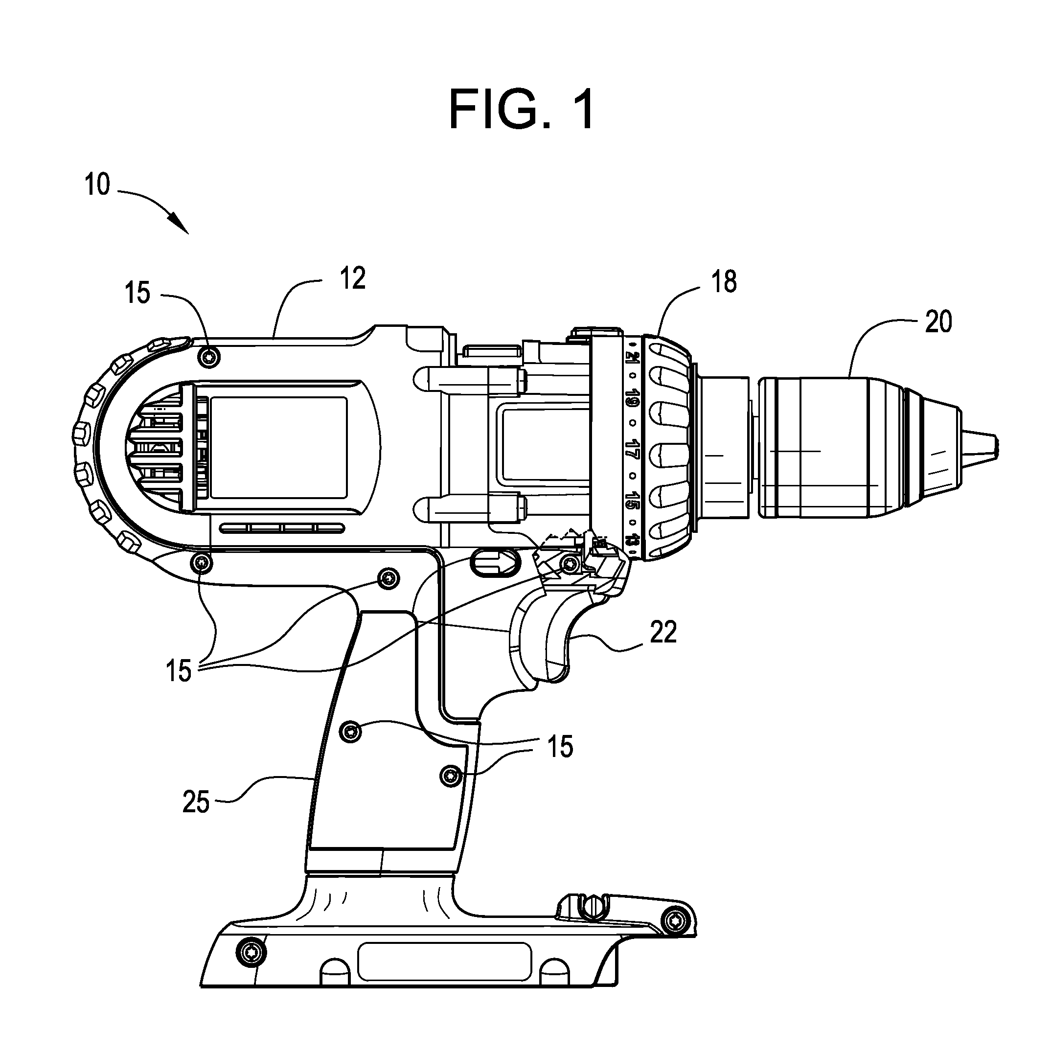
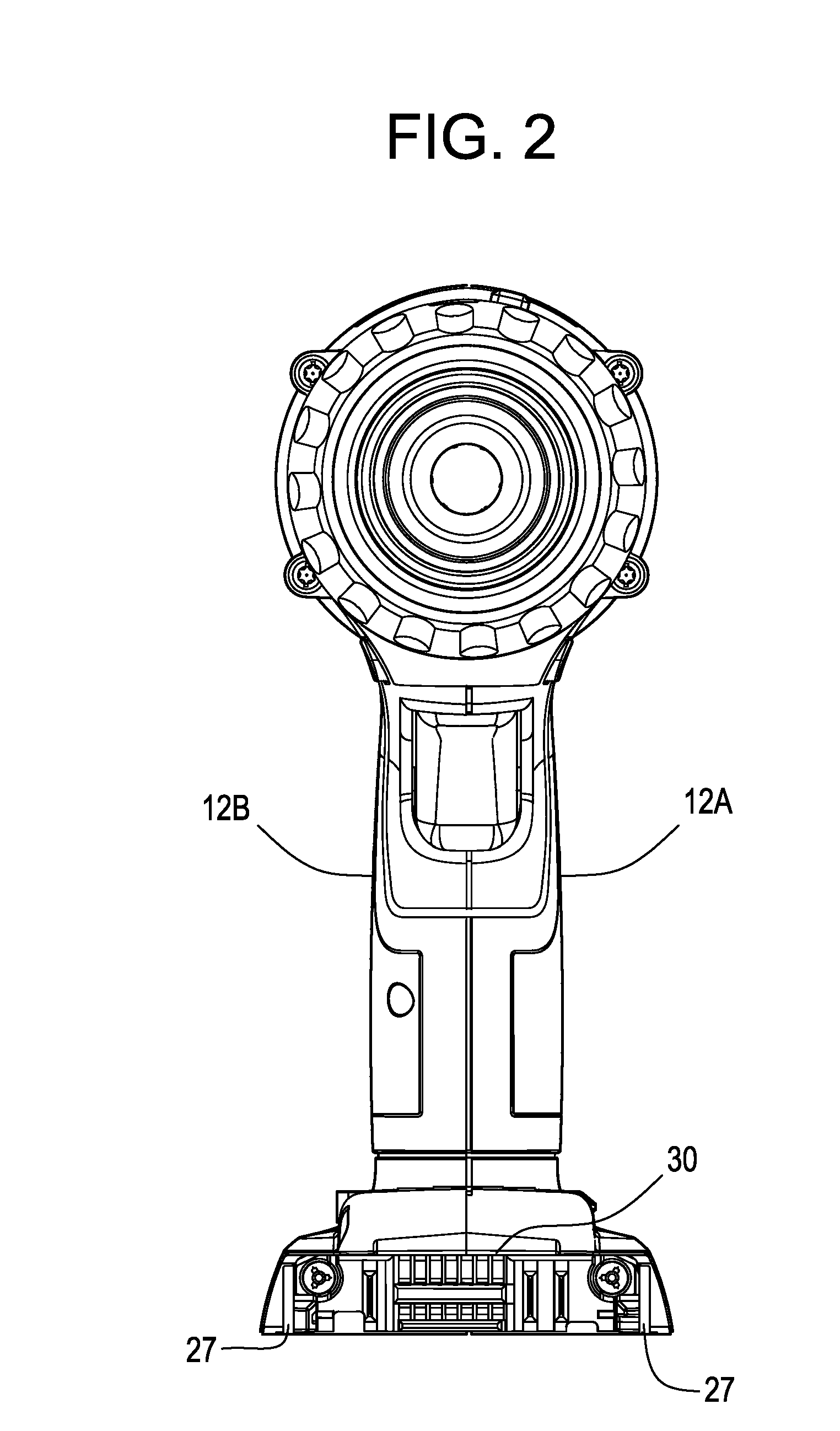
[0027]As used herein, power tools may be understood as a cordless power tool with the use of light-weight portable power sources, such as Li-ion battery packs that may provide the commensurate power with its use. Example power tools may include, but are not limited to, drills, high torque impact wrenches, single-handed metal working tools, nailers, hand planers, circular saws, jig saws, variable speed belt sanders, reciprocating saws, two handed drills such as rotary and demolition hammerdrill...


PUM


Abstract

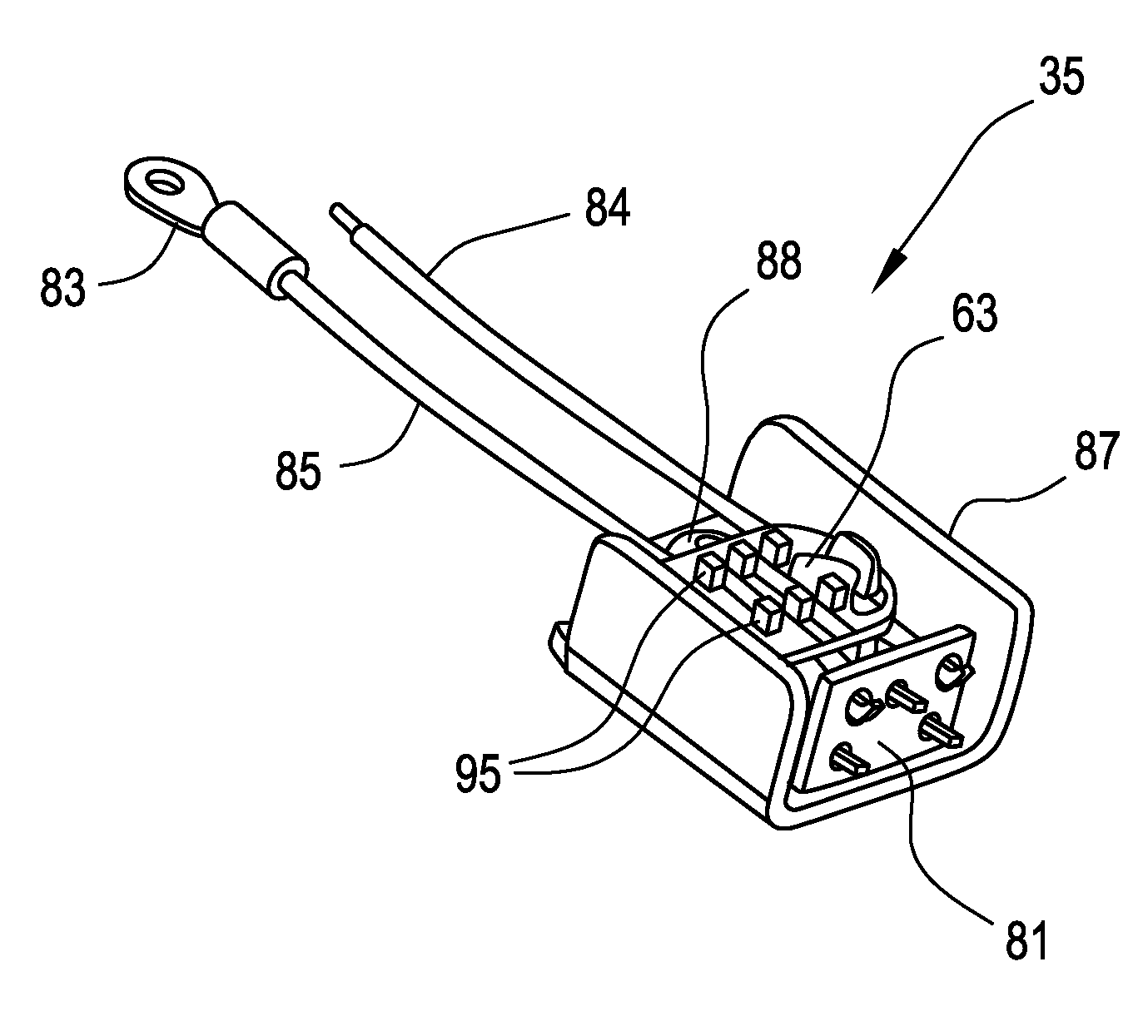
A diode assembly for a wire harness includes a printed circuit board (PCB), a diode connected to the PCB, and a plurality of diode lead wires extending from the PCB for external connections. The diode assembly includes a diode wire trap interfacing with the diode, and a heat sink in direct or indirect contact with one or more of the PCB, diode and diode wire trap for dissipating heat.

Description

PRIORITY STATEMENT[0001]This U.S. non-provisional patent application claims domestic priority under 35U.S.C. §119(e) to provisional application 60 / 731,854, filed Oct. 31, 2005, the entire contents of which are hereby incorporated by reference.BACKGROUND[0002]1. Field of the Invention[0003]Example embodiments relate generally to diodes in a wire harness for cordless power tools.[0004]2. Description of Related Art[0005]Cordless products which use rechargeable batteries are prevalent throughout the workplace as well as in the home. From house wares to power tools, rechargeable batteries are used in numerous devices. Ordinarily, nickel-cadmium (NiCd), nickel metal hydride (NiMH) and / or Lithium-ion (Li-ion) battery cells are used in these devices.[0006]Various battery technologies can be damaged when discharged in excess of the manufacturer's recommendations. Accordingly, in order to protect the battery pack, circuitry to prevent current flow is required when a battery voltage drops belo...

Claims


Application Information

Patent Timeline
Patent Type & Authority Applications(United States)
IPC IPC(8): H05K1/18
CPCH05K7/20509H01H9/061
Inventor OPSITOS, ROBERT J.
Owner AGILENT TECH INC
Learn More