Lighting apparatus

a technology of light-emitting devices and light-emitting devices, which is applied in the direction of identification means, instruments, static indicating devices, etc., can solve the problems of inability to easily update, change, or improve ic technology, and the use of ic technology for data processing is not without its drawbacks. , to achieve the effect of not incurring the burden and/or undue expense associated

Active Publication Date: 2008-07-31
LIGHTING SCI GROUP
View PDF11 Cites 6 Cited by
  • Summary
  • Abstract
  • Description
  • Claims
  • Application Information

AI Technical Summary

Benefits of technology

[0009]The foregoing needs are met, to a great extent, by the present invention, wherein in one aspect an apparatus is provided that in some embodiments will offer control over brightness levels of individual LEDs to aid in calibration of illumination networks. There is also provided in the practice of the invention, a lighting apparatus capable of being updated with new or different features without incurring the burden and / or undue expense associated with replacing hardware controller modules.

Problems solved by technology

Use of IC technology for data processing is not without its drawbacks, however.
IC controllers do not offer much in the way of flexibility because IC technology cannot be easily updated, changed, or improved once a lighting network has been put in place without considerable expense.
Large computer lighting networks present several challenges.
Particularly large computer lighting networks that have been installed for some period of time require maintenance.
Performing maintenance on such lighting networks presents special challenges when LEDs are used in certain applications such as being used as “pixels” in a video wall when it becomes necessary to replace one or more LED pixels that have burned out or have otherwise failed.
Thus, installing a new LED pixel into an area that is surrounded by older LEDs with reduced brightness results in uneven brightness of LED pixels.
Uneven pixel brightness is real problem in many large computer controlled lighting networks, such as when LEDs are used as pixels in a video wall covering a large area such as the side of a building.
Even if outright pixel failure doesn't prematurely occur, the LED pixels will eventually start to produce different levels of brightness or color over time, creating a splotchy effect.
Once installed, it is not possible to periodically perform calibration of LED brightness for individual LEDs without replacing the IC controllers used to process data.
In a large computer lighting network, replacement of IC components may not even be feasible.

Method used


Image

  • Lighting apparatus
  • Lighting apparatus
  • Lighting apparatus

Examples


Embodiment Construction

[0025]The invention will now be described with reference to the drawing figures, in which like reference numerals refer to like parts throughout. An embodiment in accordance with the present invention provides a lighting apparatus which includes a regulator configured to receive power, LEDs of at least two different colors, and a programmable controller with software that is configured to provide a digital pulse width signal to the LEDs in response to a data signal. The above description is of an embodiment of the present invention and as such, is not intended to suggest any limitation in the scope of using or functionality of the invention.

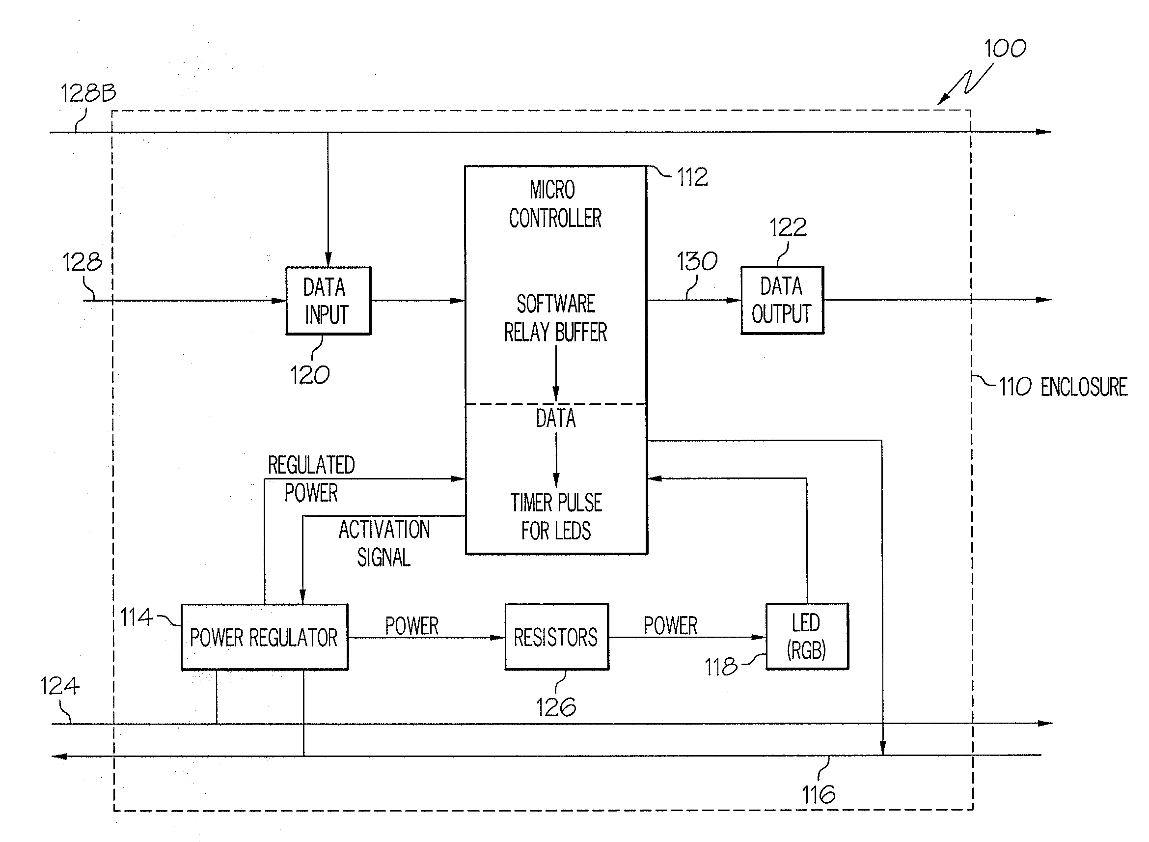
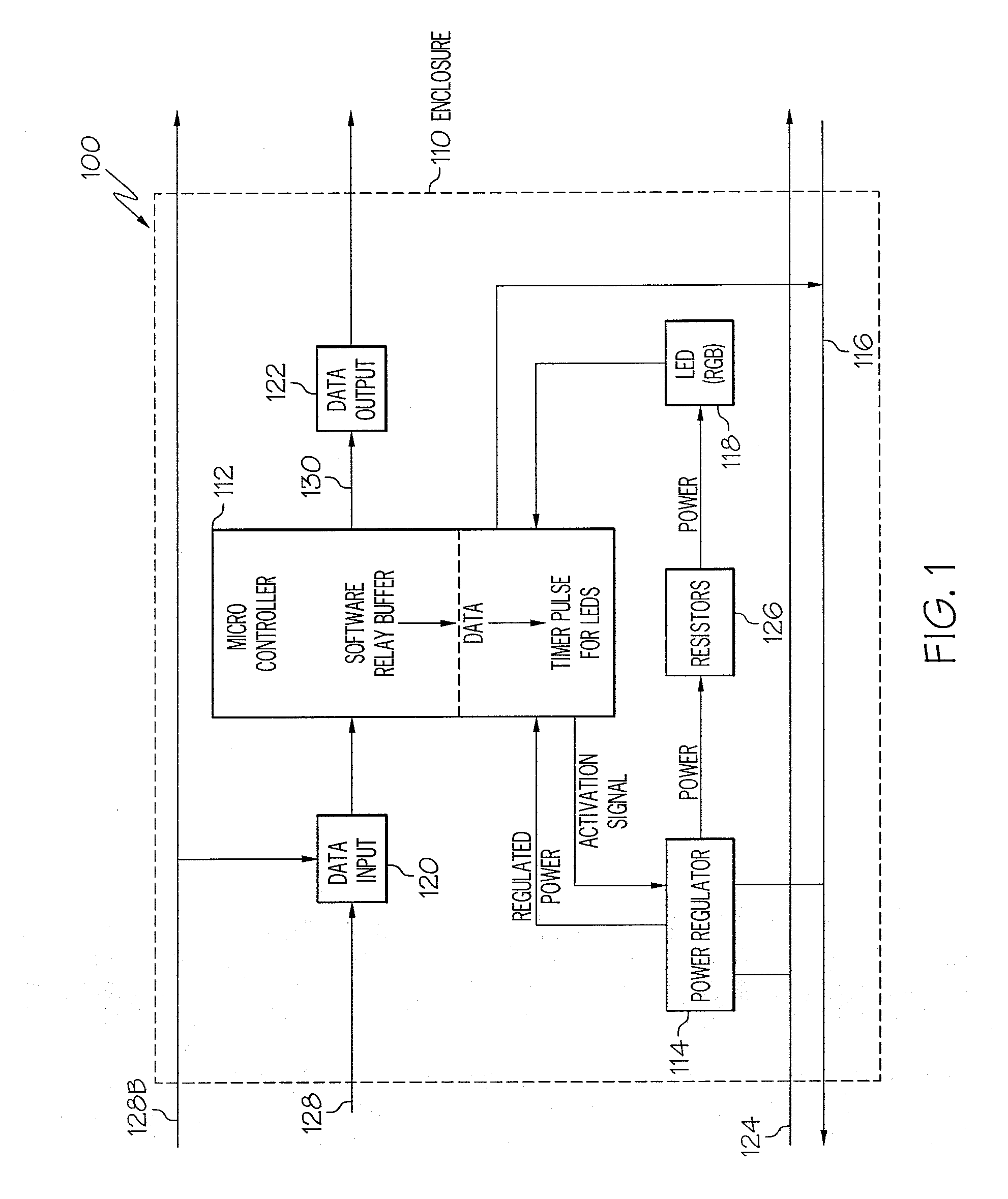
[0026]Turning to FIG. 1, shown is a block diagram of an embodiment of the lighting apparatus of the present invention. Lighting apparatus 100 is self-contained, and is configured to be interchangeable with a similarly constructed lighting apparatus. Lighting apparatus 100 features an enclosure 110 which houses components including a controller 11...


PUM


Abstract

The present invention describes a lighting apparatus which includes a regulator configured to receive power, LEDs of at least two different colors, and a programmable controller. The programmable controller includes software that is configured to provide a digital pulse width signal to the LEDs in response to a data signal. Also included is according to an embodiment of the present invention is a programmable controller with non-volatile memory for storing the software, which may be upgradeable.

Description

CROSS-REFERENCE TO RELATED APPLICATIONS[0001]None.BACKGROUND OF THE INVENTION[0002]Light emitting diodes (LEDs) have a broad range of uses in various applications. On one end of the spectrum, LEDs are used in keychain flashlights, while on the other end of the spectrum, LEDs are used in conjunction with digital control technology in complex computer lighting networks.[0003]The primary colors red, green and blue (RGB) can be combined in different proportions to generate almost any color in the visible spectrum. As a consequence, it is commonly known that combining the projected light from at least two LEDs of different primary colors can produce lighting with selectable colors.[0004]In some computer lighting networks, data signals are processed using integrated circuit (IC) controllers such as the systems described in U.S. Pat. Nos. 6,150,774 and 6,016,038 by Mueller et al., both of which are hereby incorporated by reference. Use of IC technology for data processing is not without it...

Claims


Application Information

Patent Timeline
Patent Type & Authority Applications(United States)
IPC IPC(8): G08B5/36
CPCH05B33/0842H05B37/0254H05B33/086H05B45/00H05B45/20H05B45/32H05B47/18
Inventor FURRY, KEVINSOMERVILLE, CHARLESPEAK, ERIC
Owner LIGHTING SCI GROUP
Why Eureka
Try Eureka