Multi-sensor distortion detection method and system

a multi-sensor and detection method technology, applied in the field of tracking systems, can solve problems such as magnetic field distortion, change in magnitude and direction of this field, and error in the determined location of the devi

Inactive Publication Date: 2008-07-31
GENERAL ELECTRIC CO
View PDF25 Cites 84 Cited by
  • Summary
  • Abstract
  • Description
  • Claims
  • Application Information

AI Technical Summary

Problems solved by technology

However, as those of ordinary skill in the art appreciate, the presence of field distorting objects may result in distortions in the magnetic field emitted from the EM transmitters and thereby change the magnitude and direction of this field.
For example, the presence of a signal from another source, magnetic fields of eddy current in conductive objects, or the field distorting effects of a ferro-magnetic object can result in these distortions.
Unless compensated for, these distortions will result in error in the determined location of the device.
One source of magnetic field distortions may be the equipment utilized in the tracking system itself.
As those of ordinary skill in the art will appreciate, these imaging systems typically include conducting objects (e.g., the C-arm) that result in the above-described field distortions.
This process of collecting the needed data points is time consuming and resource intensive.
However, the impact of these field distorting objects on the magnetic field in the clinical environment is generally not known, and the field distorting objects are frequently transient.
However, these techniques only detect field distortions in the immediate vicinity of the two coil assemblies and do not convey the extent of field distortions in the larger navigated volume.

Method used


Image

  • Multi-sensor distortion detection method and system
  • Multi-sensor distortion detection method and system
  • Multi-sensor distortion detection method and system

Examples


Embodiment Construction

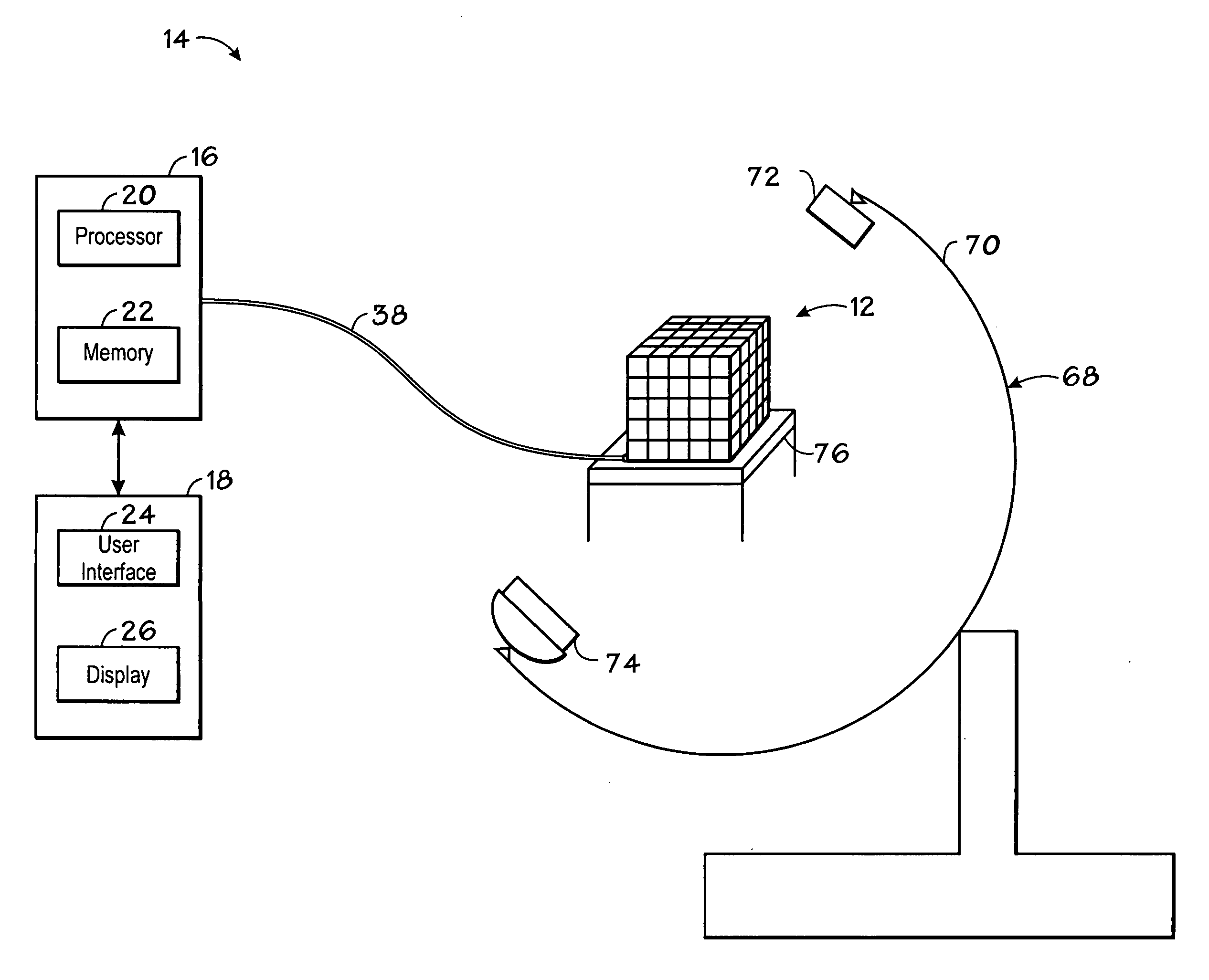
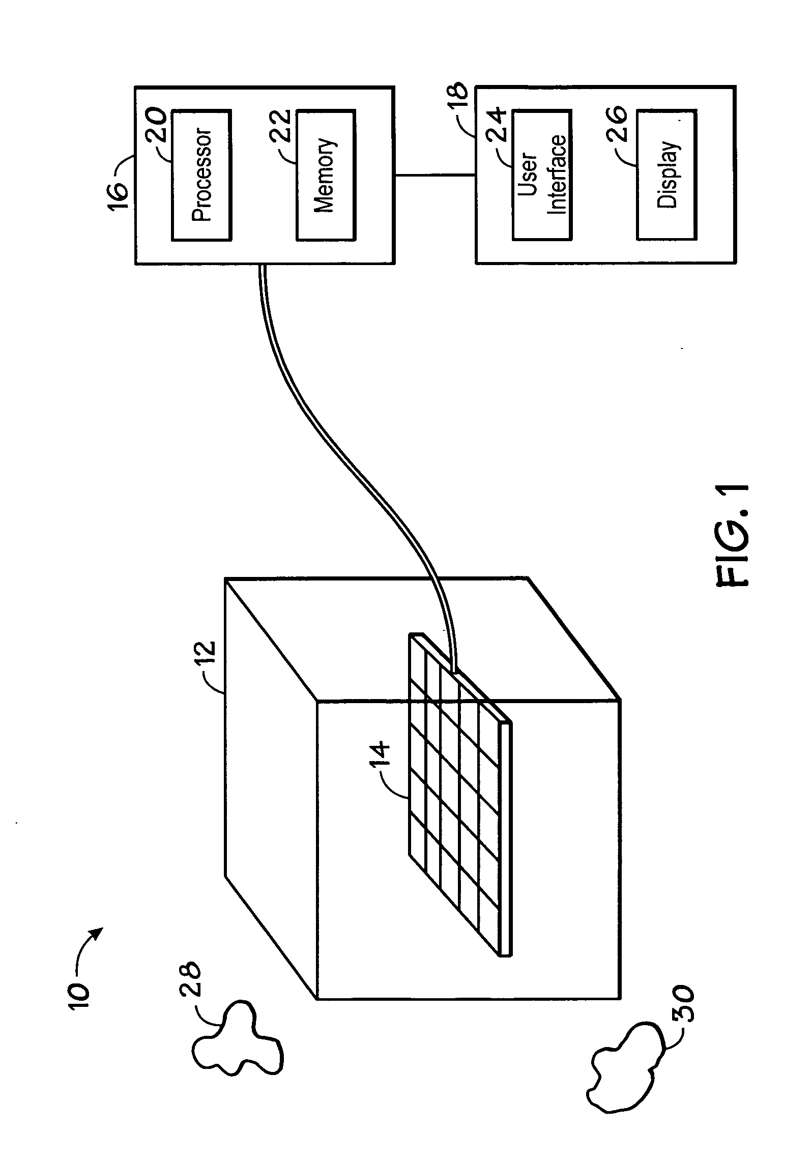
[0026]FIG. 1 illustrates diagrammatically a system 10 for detecting EM field distortion within a volume of interest 12. As illustrated, the system 10 generally includes an EM sensor assembly 14, a tracker 16, and an operator workstation 18.

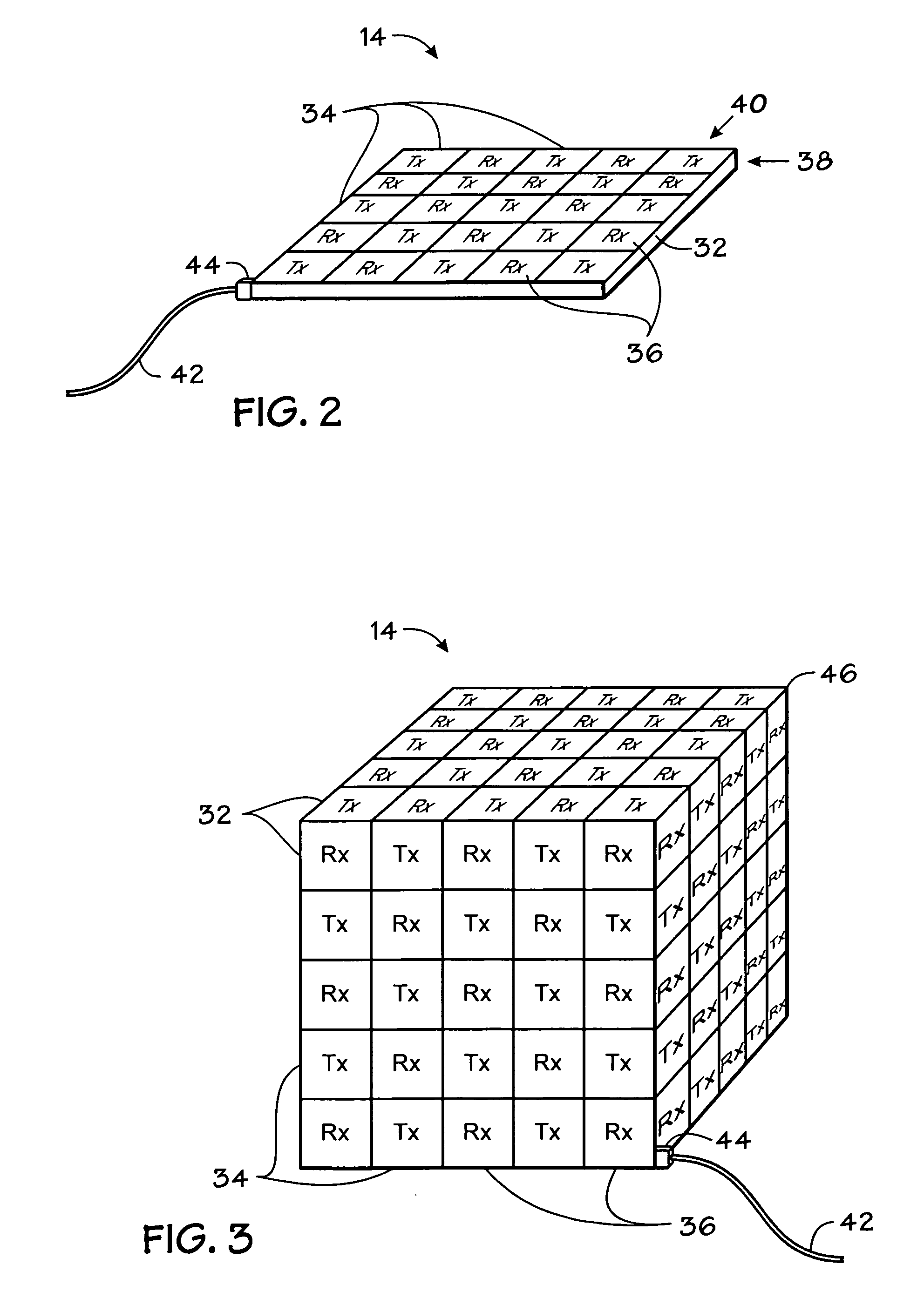
[0027]In the illustrated embodiment, an operator positions EM sensor assembly 14 within the volume of interest 12 to detect EM field distortion therein. The volume of interest 12 may be any suitable volume where it is desired to detect and / or correct for magnetic field distortions. For example, the volume of interest 12 may be a volume to be navigated by a medical device, wherein a tracking system will be used to determine the location of the medical device in the volume of interest 12. EM sensor assembly 14 generally includes a set of EM receivers and a set of EM transmitters disposed on the sensor assembly at fixed locations with respect to each other. By way of example, the EM transmitters may be implemented as field generators with each sensor...


PUM


Abstract

A method for detecting EM field distorting includes sampling a sensor assembly positioned within a volume of interest to acquire measurements of EM fields within the volume of interest, and monitoring the measurements to detect EM field distortion within the volume of interest. The sensor assembly includes a set of EM transmitters and a set of EM receivers fixed thereon. A system for detecting EM field distorting includes a sensor assembly for positioning within a volume of interest, wherein the EM sensor assembly comprises a set of EM receivers, and a set of EM transmitters, wherein the EM receivers and the EM transmitters are disposed at fixed locations on the sensor assembly. The system further includes a tracker configured to sample the sensor assembly to acquire measurements of EM fields generated by the EM transmitters, and monitor the measurements to detect EM field distortion within the volume of interest.

Description

BACKGROUND[0001]This disclosure relates generally to tracking systems that use magnetic fields, such as for surgical interventions and other medical procedures. More particularly, this disclosure relates to an apparatus and method for detecting magnetic field distortion in such systems.[0002]Tracking systems have been used to provide an operator (e.g., a physician) with information to assist in the precise and rapid positioning of a medical (e.g., surgical) device in a patient's body. In general, an image is displayed for the operator that includes a visualization of the patient's anatomy with an icon or image representing the device superimposed thereon. As the device is positioned with respect to the patient's body, the displayed image is updated to reflect the correct device coordinates. The image of the patient's anatomy may be generated either prior to or during the medical or surgical procedure. Moreover, any suitable medical imaging technique, such as X-ray, computed tomograp...

Claims


Application Information

Patent Timeline
Patent Type & Authority Applications(United States)
IPC IPC(8): A61B5/00G01B7/00
CPCA61B5/06G01R29/0814G01B7/003A61B5/6814A61B5/062
Inventor CHANDONNET, JASON RENEJENSEN, VERNON THOMASLEA, JON THOMAS
Owner GENERAL ELECTRIC CO
Why Eureka
Try Eureka