Fuel injection system with cross-flow nozzle for enhanced compressed natural gas jet spray

a technology of compressed natural gas and injection system, which is applied in the direction of combustion air/fuel air treatment, machines/engines, mechanical equipment, etc., can solve the problems of drivability problems and conventional cng injector designs that have not achieved suitable combustion, and achieve the effect of improving the mixing characteristics of gaseous fuel

Inactive Publication Date: 2008-08-07
CONTINENTAL AUTOMOTIVE SYST INC
View PDF21 Cites 14 Cited by
  • Summary
  • Abstract
  • Description
  • Claims
  • Application Information

AI Technical Summary

Benefits of technology

[0004]The present invention provides improved gaseous fuel targeting and fuel distribution with an intake manifold system. Back-flow of the air-fuel mixture into the internal combustion engine's intake plenum or into other engine cylinders may be avoided by providing a discharge pattern that forms a cloud of CNG inside the intake manifold. The discharge pattern of CNG delivered to the intake manifold of the present invention is believed to improve the air-fuel mixture and drivability problems that are believed to be in the prior art.
[0007]In yet another aspect of the present invention, a method of metering gaseous fuel in an intake manifold having a gaseous fuel supply connected to a fuel injector is provided. The resulting discharge pattern of the gaseous fuel improves the mixing characteristics of the gaseous fuel within the intake manifold. The method can be achieved by: flowing air from an inlet to an outlet through a passage of an intake manifold; flowing gaseous fuel from the gaseous fuel supply to an inlet end of the fuel injector; and forming a generally ellipsoidal gaseous fuel spray pattern proximate the outlet in the passage of the intake manifold.

Problems solved by technology

It is believed that some conventional CNG injector designs have failed to achieve suitable the combustion of gaseous fuel injected into the intake manifold of an internal combustion engine.
Specifically, such design of CNG injectors may reduce air flow or even cause back-flow of the air-fuel mixture into the internal combustion engine's intake plenum or into other engine cylinders thereby causing drivability problems.

Method used


Image

  • Fuel injection system with cross-flow nozzle for enhanced compressed natural gas jet spray
  • Fuel injection system with cross-flow nozzle for enhanced compressed natural gas jet spray
  • Fuel injection system with cross-flow nozzle for enhanced compressed natural gas jet spray

Examples


Embodiment Construction

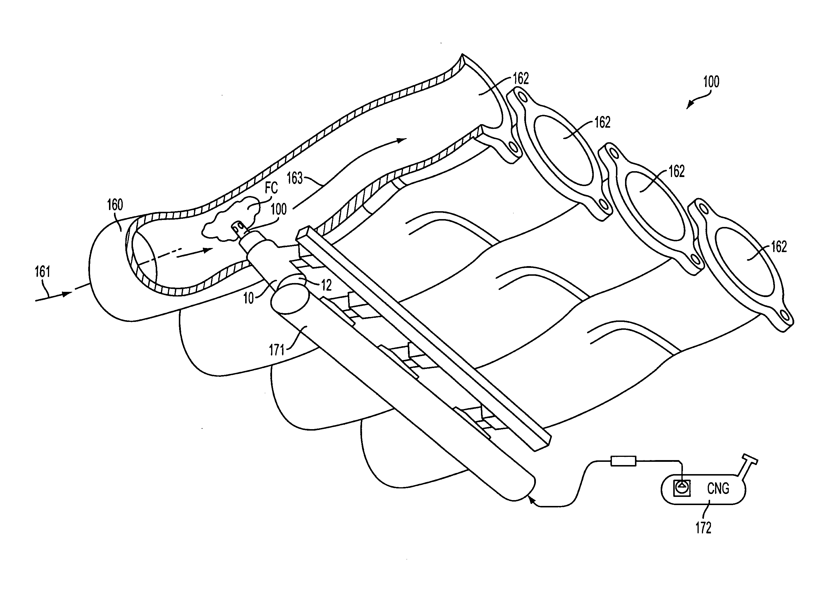
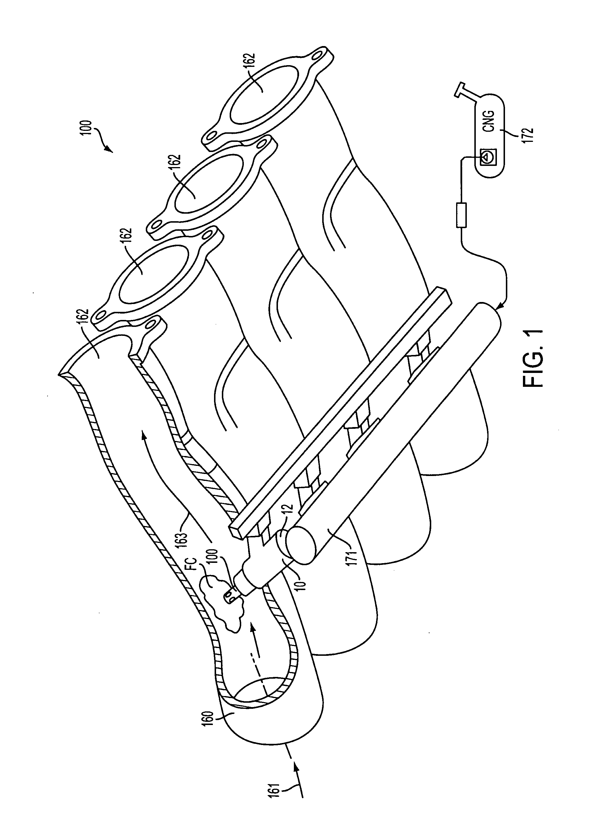
[0012]FIGS. 1-3 illustrate the preferred embodiments. In particular, FIG. 1 illustrates an intake manifold system 180 comprising an intake manifold 160 and a CNG fuel injector 10. A fuel rail 171 and a CNG fuel supply 172 are shown, but are not considered part of the intake manifold system 180.

[0013]The intake manifold 160 directs an air flow from an inlet 161 to an outlet 162. Outlets 162 are substantially tubular in shape and generally bolt to an engine block, not shown. The intake manifold provides combustion air to the combustion chamber(s) of the engine. The intake manifold 160 may be made of a metallic material, plastic, or other composite material. The intake manifold is preferably made of plastic, most preferably nylon 6-6.

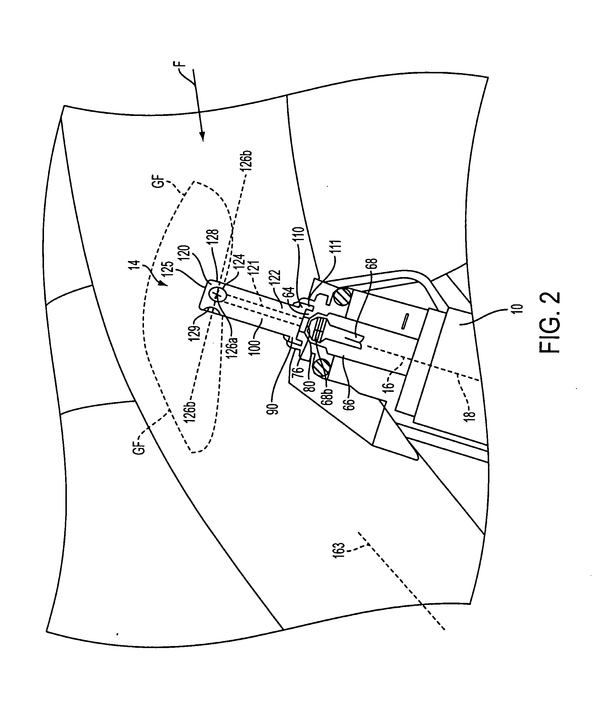
[0014]The CNG fuel injector 10 has a housing, which includes a fuel inlet 12, a fuel outlet 14, and a fuel passageway 16 extending from the inlet 12 to the outlet 14 along a longitudinal axis 18. The fuel outlet 14 of the CNG fuel injector 10 is located pa...


PUM


Abstract

An intake manifold system including an intake manifold and a compressed natural gas (CNG) fuel injector located between an inlet and an outlet of the intake manifold. The CNG fuel injector includes a housing, an inlet, an outlet, a seat, a closure member, and a nozzle. In a preferred embodiment, the inlet and outlet communicate a flow of gaseous fuel regulated by the closure member. The gaseous fuel passes through the seat, which is secured to a rim surface of a retainer portion of the nozzle, and into a flow passage that further communicates the flow of gaseous fuel into one or more flow channels. The orientation of the flow channels within the nozzle greatly affects the discharge pattern and mixing characteristics of the gaseous fuel within an intake manifold. A method of metering gaseous fuel in an intake manifold having a gaseous fuel supply coupled to a fuel injector is also described.

Description

[0001]This application is a continuation of commonly-assigned, copending application Ser. No. 11 / 428,962, filed on Jul. 6, 2006.BACKGROUND OF INVENTION[0002]In the case of internal combustion engines having injection systems, fuel injectors are conventionally used to provide a precise amount of fuel needed for combustion. Compressed natural gas (hereinafter sometimes referred to as “CNG”) is a common automotive fuel for commercial fleet vehicles and residential customers. In vehicles, the CNG is delivered to the engine in precise amounts through fuel injectors, hereinafter referred to as “CNG injectors”, or simply “fuel injectors.” CNG injectors of this type are described in commonly assigned U.S. Pat. No. 5,494,224, the disclosure of which is incorporated by reference herein. Typically, the CNG injector is required to deliver the precise amount of fuel per injection pulse and maintain this accuracy over the life of the injector. In order to improve the combustion of fuel, certain s...

Claims


Application Information

Patent Timeline
Patent Type & Authority Applications(United States)
IPC IPC(8): F02M61/14
CPCY02T10/32F02M21/0245F02M21/0278F02M21/0281F02M21/0263Y02T10/30
Inventor PARISH, JAMES R.
Owner CONTINENTAL AUTOMOTIVE SYST INC
Why Eureka
Try Eureka