
Fixing roller and image forming apparatus

Active Publication Date: 2008-08-07
SHARP KK
View PDF14 Cites 0 Cited by
  • Summary
  • Abstract
  • Description
  • Claims
  • Application Information

AI Technical Summary

Benefits of technology

[0012]An object of the present invention is to provide a fixing roller which is used in an image forming apparatus with a high process speed (300

Problems solved by technology

However, the above fixing roller has inconvenience.
When the fixing roller is used in a high-speed printer whose process speed (peripheral velocity of the fixing roller) is 300 mm/s or more, mechanical and thermal stress applied on the PFA tube is large, resulting in occurrence of wrinkles on the PFA tube.
The reason is as follows: making the PFA tube thicker reduces flexibility of the PFA tube, and accordingly the PFA tube cannot sufficiently follow deformation of the silicone rubber, resulting in occurrence of shearing stress between the PFA tube and

Method used


Image

  • Fixing roller and image forming apparatus
  • Fixing roller and image forming apparatus
  • Fixing roller and image forming apparatus

Examples


Example

[0107]However, the result of the comparative example 1 shows that the fixing roller having a PFA tube with a thickness of 30 μm has a problem that use of the fixing roller with a process speed of 300 mm / s or more generates wrinkles on the PFA tube. This is because a higher process speed enlarges mechanical and thermal stress applied on the PFA tube.

[0108]Further, the results of the comparative examples 2 and 3 show that, in order to prevent wrinkles on the PFA tube of the fixing roller, it is effective to increase mechanical strength of the PFA tube by setting the thickness of the PFA tube to be 40 μm or more. However, the results also show that thicker PFA tube is more likely to be detached from the silicone rubber. The reason is as follows: making the PFA tube thicker reduces flexibility of the PFA tube, and accordingly the PFA tube cannot sufficiently follow deformation of the silicone rubber, resulting in larger shearing stress at an interface between the PFA tube and the silico...


PUM


Abstract

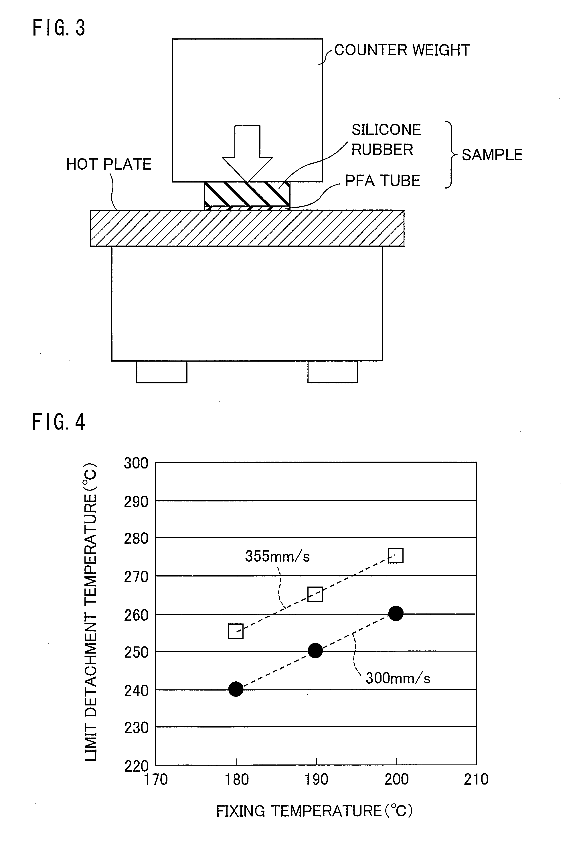
A fixing roller includes: a core; an elastic layer made of an elastic material, formed around the core; and a resin layer made of fluorine resin, formed around the elastic layer. The fixing roller is designed such that the resin layer has a thickness of 40 μm or more, and the fixing roller meets a relation Tr≧Tc+60 or Tr≧Tc+75 where Tr (° C.) is a limit temperature obtained in a predetermined peeling test and Tc (° C.) is a temperature of the fixing roller at which a fixing process is performed. This allows the fixing roller used in an image forming apparatus with a high process speed to secure that the resin layer is less likely to be detached from the elastic layer.

Description

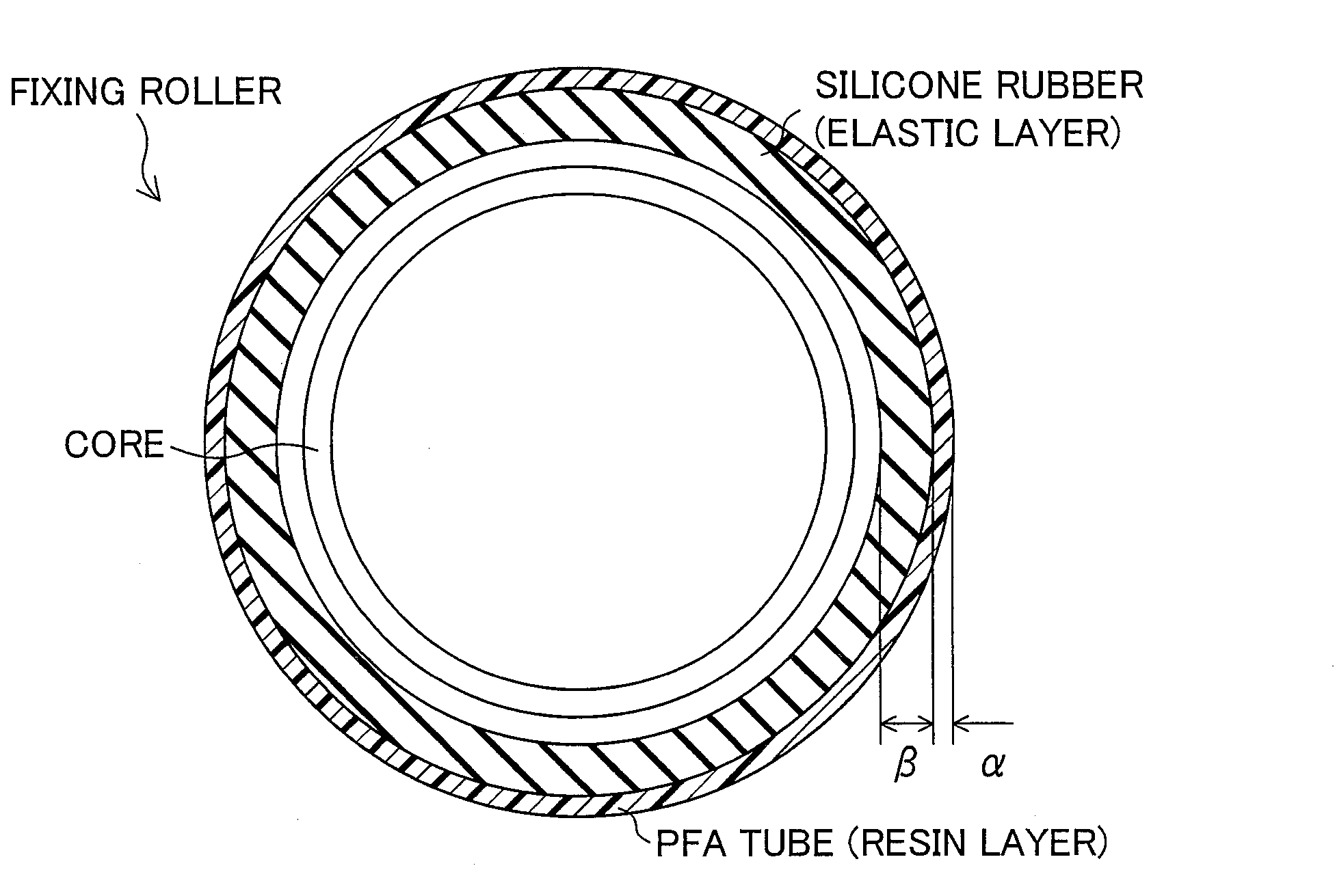
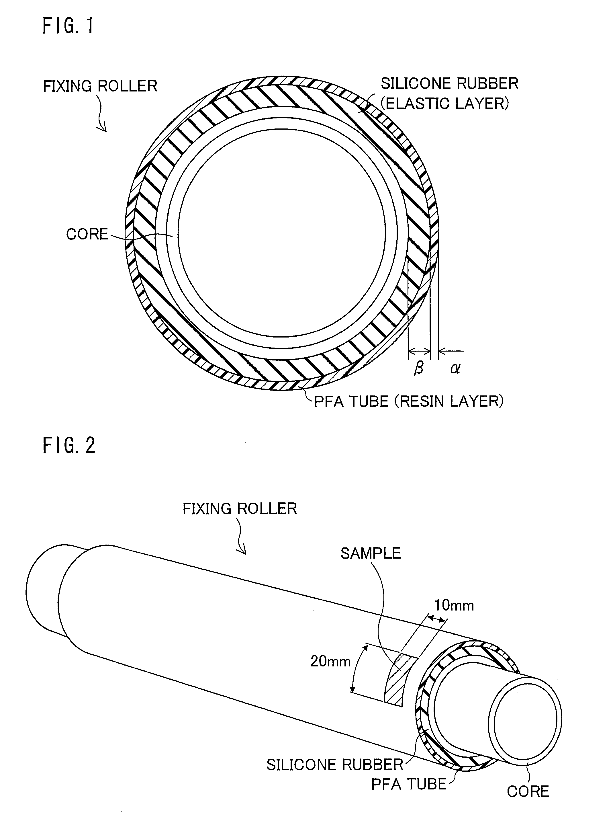
[0001]This non-provisional application claims priority under 35 U.S.C. §119(a) on Patent Application No. 2007-024786 filed in Japan on Feb. 2, 2007, the entire contents of which are hereby incorporated by reference.FIELD OF THE INVENTION[0002]The present invention relates to a fixing roller that is a component of a fixing apparatus included in an electrophotographic image forming apparatus.BACKGROUND OF THE INVENTION[0003]In general, a fixing roller used in an electrophotographic image forming apparatus (e.g. a copying machine, a multifunctional apparatus, and a printer), particularly a fixing roller used in a color printer, includes a structure in which an elastic layer made of silicone rubber is formed around a metal core and a resin layer (surface layer) made of a PFA tube is provided around the elastic layer.[0004]The fixing roller coated with the PFA tube is produced in such a manner that a PFA tube whose internal surface has been subjected to an etching treatment and to applic...

Claims


Application Information

Patent Timeline
IPC IPC(8): G03G15/20
CPCG03G15/2057
Inventor KAGAWA, TOSHIAKI
Owner SHARP KK
Learn More