Cycloid limited slip differential and method

a limited slip differential and cycloid technology, applied in the field of differentials, can solve the problems of high cost, heavy bevel gears, and high cost of limited slip differentials containing bevel gears

Inactive Publication Date: 2008-08-07
GM GLOBAL TECH OPERATIONS LLC
View PDF4 Cites 16 Cited by
  • Summary
  • Abstract
  • Description
  • Claims
  • Application Information

AI Technical Summary

Problems solved by technology

However, bevel gears tend to be heavy, and the manufacture of limited slip differentials (LSDs) containing bevel gears is therefore relatively expensive.
As a result, systems having such gear designs, including LSDs having add-ons such as multi-disk and / or viscous coupling, tend to carry a cost premium, and may be less than optimal in terms of size, weight, and smoothness of function.

Method used


Image

  • Cycloid limited slip differential and method
  • Cycloid limited slip differential and method
  • Cycloid limited slip differential and method

Examples


Embodiment Construction

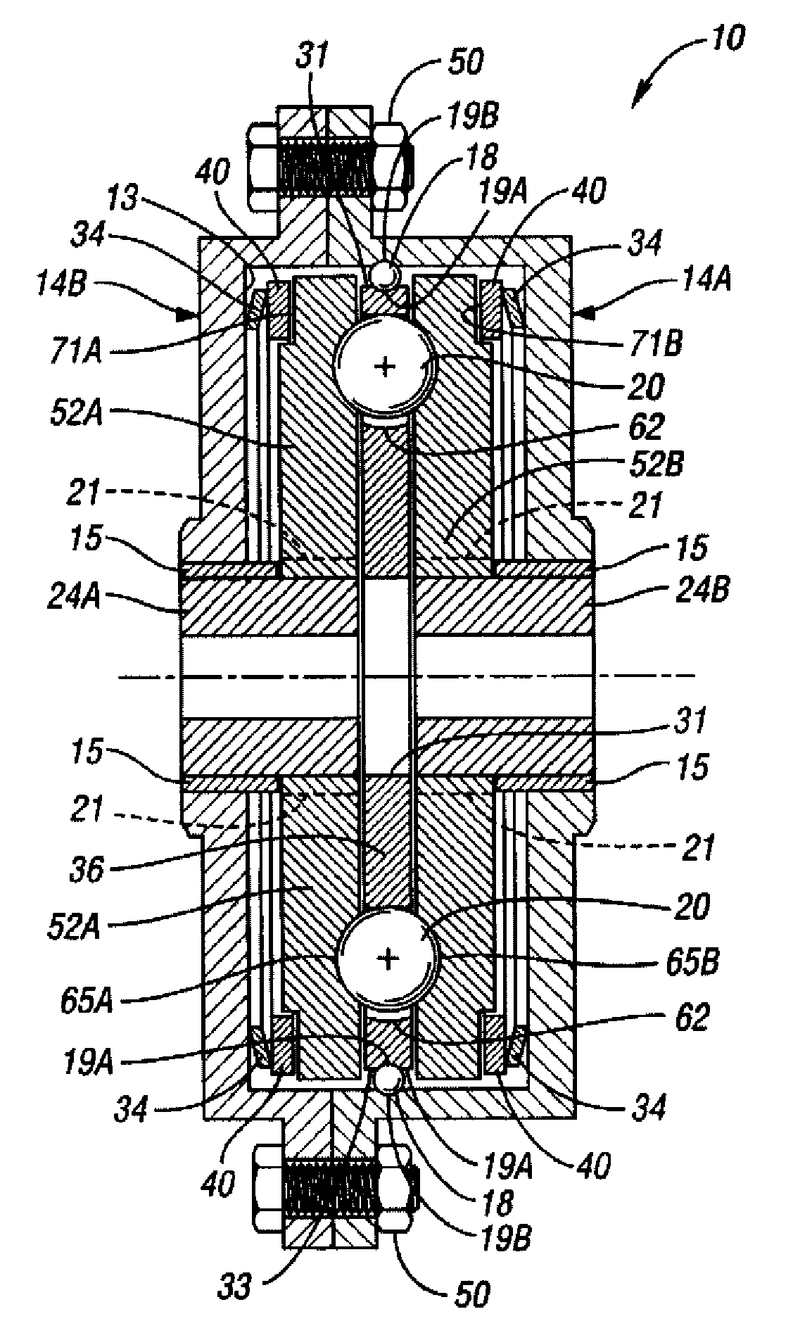
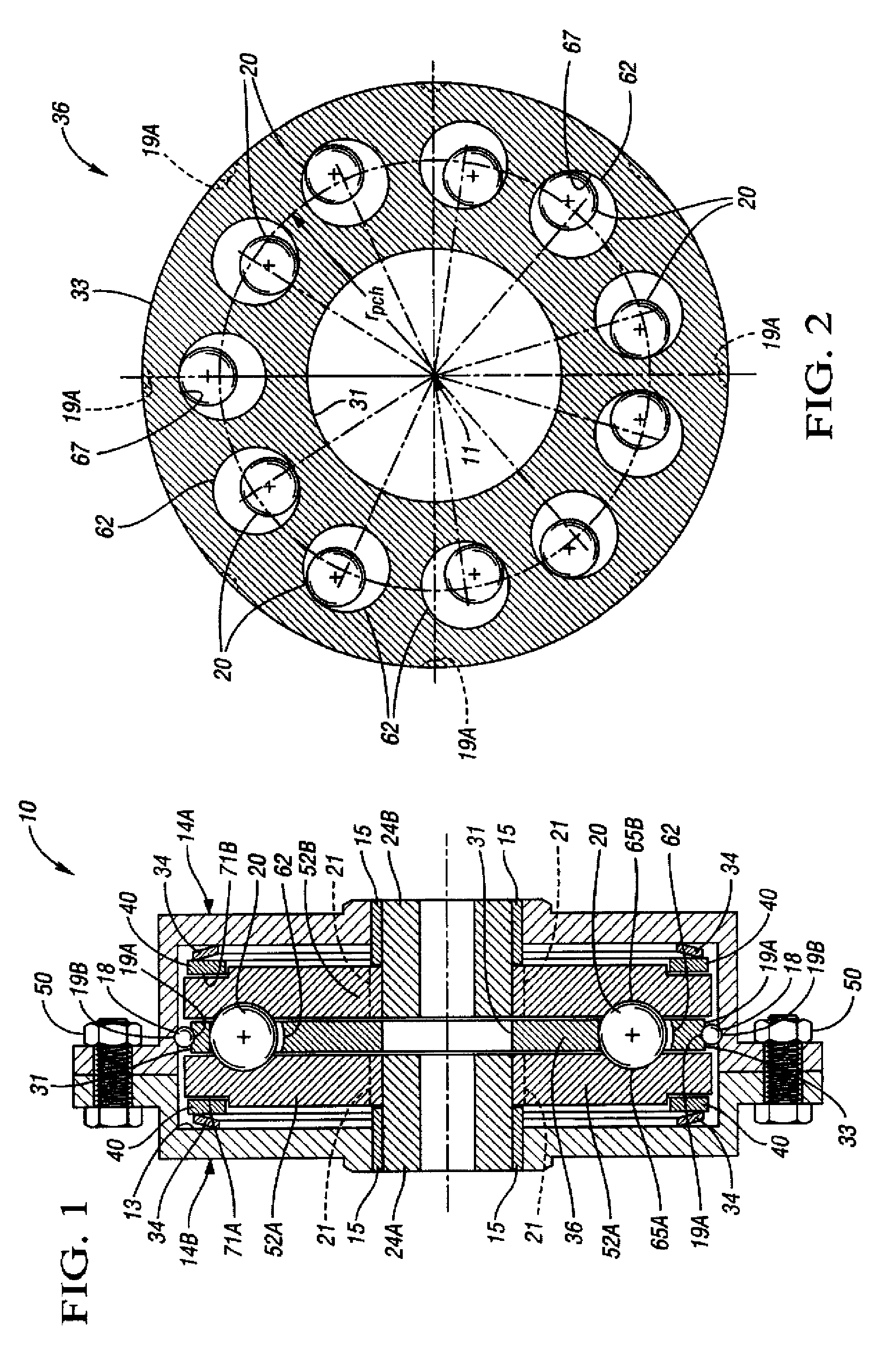
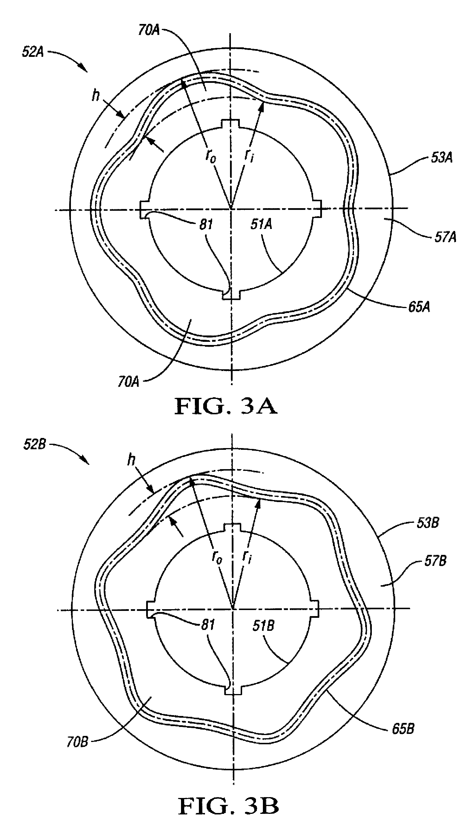
[0016]Referring to the drawings wherein like reference numbers correspond to like or similar components throughout the several figures, there is shown in FIG. 1 a cross-sectional view of a cycloid limited-slip differential 10 according to the invention. The differential 10 has a rotatable two-piece outer member, case, or housing 14A, 14B that is cast or otherwise formed and connected by bolts 50 or other suitable fasteners to form a unitary piece. The assembled housing 14A and 14B, hereinafter referred to as housing 14 for simplicity, is operatively attached to a rotatable drive member (not shown), such as a transmission drive shaft, so that the housing 14 rotates in conjunction with the drive member. The housing 14 has an inner wall 13 and at least partially encloses a first and second cycloid plate or disk 52A, 52B, respectively, with each of disks 52A and 52B positioned or oriented to face an opposite or opposing face or side of a center coupling disk 36. A compressible Bellevill...


PUM


Abstract

A differential is provided comprising a rotatable differential housing, first and second output members, a first cycloid disk having an epitrochoid groove, a second cycloid disk having a hypotrochoid groove, a coupling disk connected having a plurality of holes each containing a sphere, wherein the spheres are engageable with the grooves for transferring torque between the cycloid disks. A method is also provided for distributing torque in a vehicle having two axles including at least one drive axle, including attaching one axle to a cycloid disk having a continuous epitrochoid groove, attaching another axle to a cycloid disk having a continuous hypotrochoid groove, attaching a rotatable housing to a center coupling disk having a plurality of holes, and positioning a torque transfer sphere that is engageable with the grooves in each of the holes, wherein the spheres are configured for distributing torque along the drive axles.

Description

TECHNICAL FIELD[0001]The present invention relates generally to a differential for distributing torque within a vehicle, and particularly to a cycloid differential having two cycloid disks that are mutually engageable via a plurality of spheres positioned within a center coupling disk.BACKGROUND OF THE INVENTION[0002]In vehicles having multiple drive axles, such as vehicles having full-time or automatic all-wheel drive (AWD) transmissions, the wheels on one drive axle at times must rotate or spin at a different relative speed than the wheels on the other drive axle in order to limit slippage due to poor traction at the road interface near one or more tires, such as when the vehicle passes over a patch of ice. Also, at times a wheel on one side of a drive axle of an AWD, front-wheel, or rear-wheel drive vehicle might need to rotate or spin at a different rate from that of the wheel disposed on the other side of the same drive axle, such as when the vehicle is turning.[0003]To enable ...

Claims


Application Information

Patent Timeline
Patent Type & Authority Applications(United States)
IPC IPC(8): F16H13/06F16H48/12
CPCF16H25/06F16H48/147F16H48/14
Inventor MIAO, HSU-CHIANGKAO, CHI-KUAN
Owner GM GLOBAL TECH OPERATIONS LLC
Why Eureka
Try Eureka