
Anchoring System for Fixing Objects to Bones

a technology of fixing system and bone, which is applied in the field of bone fixing system plate, can solve the problems of destabilizing the spinal column, pain and/or nerve damage, altering the natural separation between adjacent vertebrae, etc., and achieves the effect of facilitating the accurate placement of the first vertebrae and increasing spinal stability

Inactive Publication Date: 2008-08-07
ORTHOPLEX
View PDF0 Cites 15 Cited by
  • Summary
  • Abstract
  • Description
  • Claims
  • Application Information

AI Technical Summary

Benefits of technology

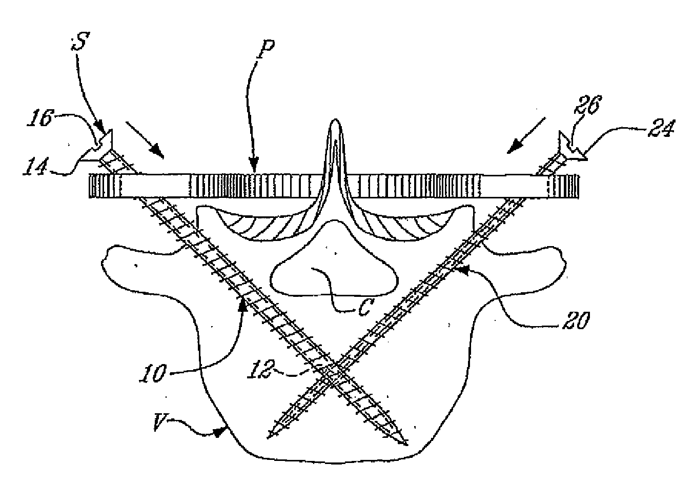
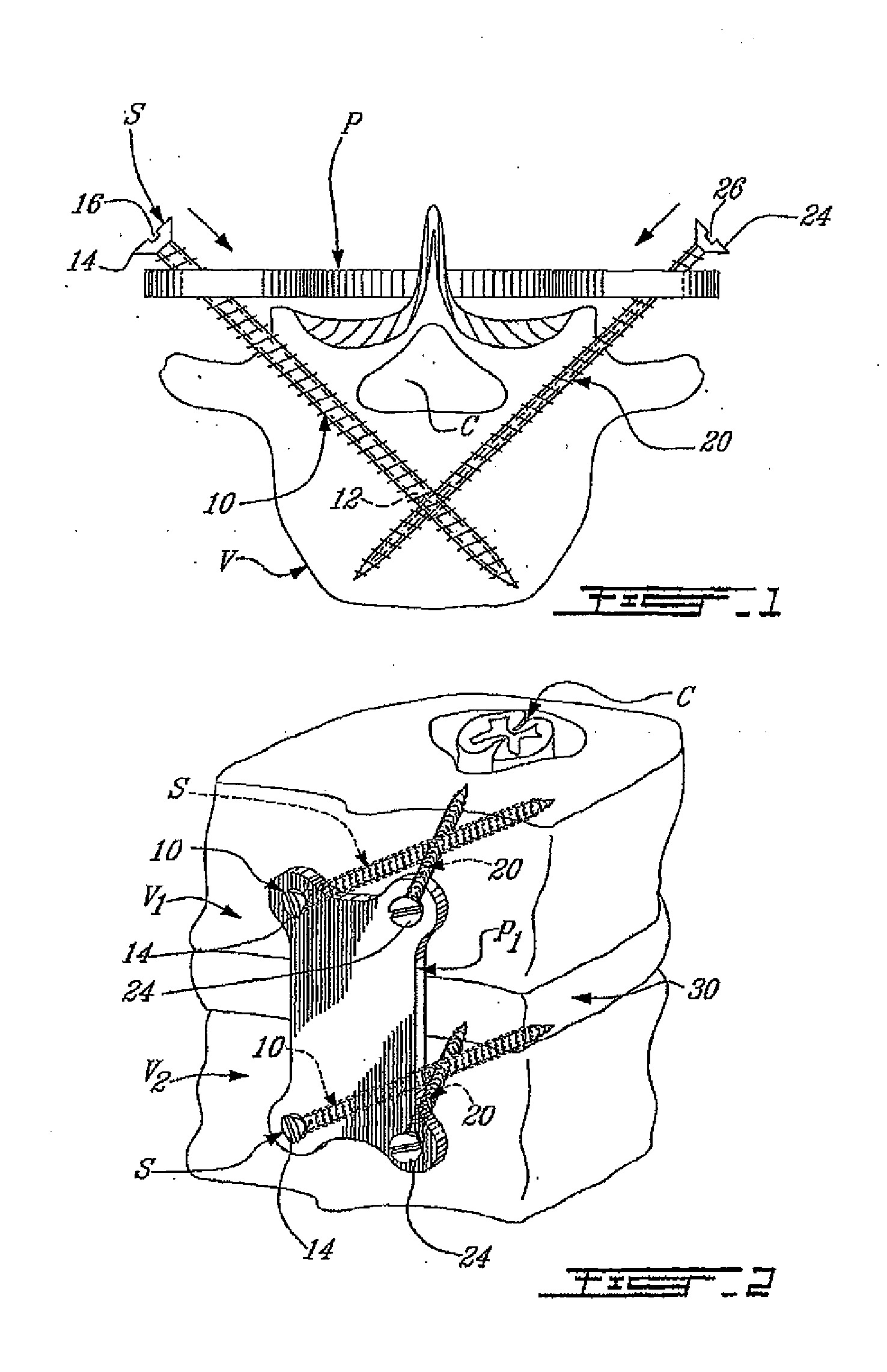
[0015]A spinal plate system that allows for increased spinal stability is provided. In an embodiment, a spinal plate system is provided that includes first and second slidable plates coupled together. Each of the first and second slidable plates includes first and second fasteners that are obliquely oriented relative to the corresponding slidable plate. The first and second fasteners are fixed to each other at their distal ends thereby forming a triangular frame consisting of the corresponding slidable plate and the first and second fasteners. In addition, a fastener guide is provided that facilitates the accurate placement of the first and second fasteners for each of the first and second slidable plates.

Problems solved by technology

Partial or full removal of a vertebrae disk may destabilize the spinal column and may alter the natural separation between adjacent vertebrae.
Excessive pressure applied to the nerves may cause pain and / or nerve damage.
The current art for fastening plates to spinal vertebrae has at least one major problem: loosening of the fasteners.
This loosening may be caused by resultant biomechanical forces, micro motions of the plate system and fasteners, or the poor quality of osteoporotic bone.
The inability for a bone screw to properly purchase into the osteoporotic bone is a major problem for older patients, leading to loosening of the spinal plates and increasing the possibility of having the older patient undergo a second operation to reposition or otherwise retighten the spinal plates.

Method used


Image

  • Anchoring System for Fixing Objects to Bones
  • Anchoring System for Fixing Objects to Bones
  • Anchoring System for Fixing Objects to Bones

Examples


Embodiment Construction

[0025]The following detailed description sets forth numerous specific details to provide a thorough understanding of the invention. However, those skilled in the art will appreciate that the invention may be practiced without these specific details. In other instances, well-known methods, procedures, components, protocols, processes, and circuits have not been describe in detail so as not to obscure the invention.

[0026]A spinal plate system that may be used to stabilize a portion of a spinal column and a method of use are described in more detail below. The spinal plate system includes first and second plates that are slidably coupled to one another and allow for motion of each of the plates relative to the other. Each of the first and second plates is secured to the bone by an obliquely oriented post and screw system wherein the post and screw are oriented so as to converge to one another. The post includes an oblique threaded hole that receives the distal portion of the screw. In ...


PUM


Abstract

A spinal plate system that allows for increased spinal stability is provided. In an embodiment, a spinal plate system is provided that includes first and second slidable plates coupled together. Each of the first and second slidable plates includes first and second fasteners that are obliquely oriented relative to the corresponding slidable plate. The first and second fasteners are fixed to each other at their distal ends thereby forming a triangular frame consisting of the corresponding slidable plate and the first and second fasteners. In addition, a fastener guide is provided that facilitates the accurate placement of the first and second fasteners for each of the first and second slidable plates.

Description

CROSS REFERENCE TO RELATED APPLICATIONS[0001]This application is a continuation-in-part of US Non-Provisional Patent application, Ser. No. 10 / 275,710 filed May 25, 2001, which is incorporated herein by reference, that was the US National Phase of international application PCT / CA01 / 00751 filed May 25, 2001 which designated the US and which claims priority to Provisional Application, Ser. No. 60 / 206,811 filed on May 25, 2000. and is also continuation-in-part of US Non-Provisional Patent application, Ser. No. 10 / 358,398, which is incorporated herein by reference, filed Feb. 5, 2003 that is a continuation in part of U.S. Ser. No. 10 / 296,392 filed Nov. 25, 2002 which is a National Entry of PCT / CA01 / 00739 filed on May 25, 2001 and claiming priority to US Provisional Applications Ser. No. 60 / 206,810 filed on May 25, 2000 and Ser. No. 60 / 264,309 filed Jan. 29. 2001BACKGROUND OF THE INVENTION[0002]1. Field of the Invention[0003]The present invention relates generally relates to a bone fixati...

Claims


Application Information

Patent Timeline
Patent Type & Authority Applications(United States)
IPC IPC(8): A61B17/58A61B17/56
CPCA61B17/1728A61B17/1735A61B17/1757A61B2019/444A61B17/8023A61B17/8625A61B2017/8655A61B17/7059A61B90/92
Inventor SEVRAIN, LIONEL C.
Owner ORTHOPLEX
Learn More