Guide disc attachment for snow blower housing

Inactive Publication Date: 2008-08-14
LUHTANEN JAMES L
View PDF20 Cites 11 Cited by
  • Summary
  • Abstract
  • Description
  • Claims
  • Application Information

AI Technical Summary

Benefits of technology

[0008]The present invention has been designed to overcome the shortcomings in the prior art noted above. The invention primarily consists of a pair of rigid, narrow discs, mounted in tandem, one on each side, on a snow blower bin and housing. Each disc is mounted on, and rotates about, an axle perpendicular to the side of the housing, and in parallel with the cutting edge of the snow blower. The rigid, narrow features of the disc permit it to cut or break through impacted snow and ice, and to reach and contact the hard surface lying beneath the snow or ice which i

Problems solved by technology

As stated, these designs, commonly used by modern day manufacturers of snow blowers, tend to ride up on top of the snow and may even themselves impact the snow, exacerbating the “ride up” tendency by their very operation.
The problem with impacted snow and ice is compounded as the winter season continues, and the snow and/or ice pack becomes thicker.
An additional problem, not addressed by current sno

Method used


Image

  • Guide disc attachment for snow blower housing
  • Guide disc attachment for snow blower housing
  • Guide disc attachment for snow blower housing

Examples


Embodiment Construction

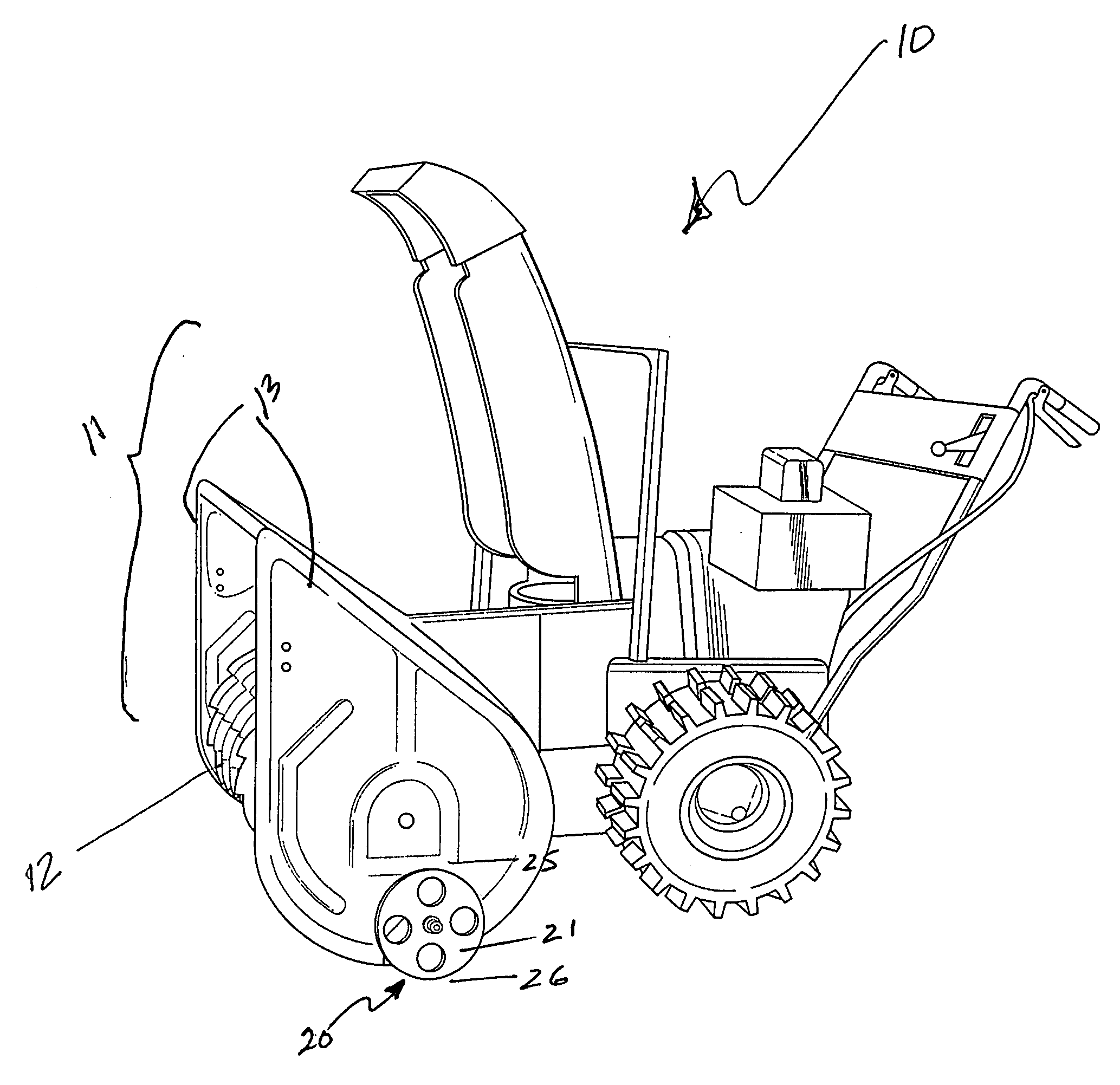
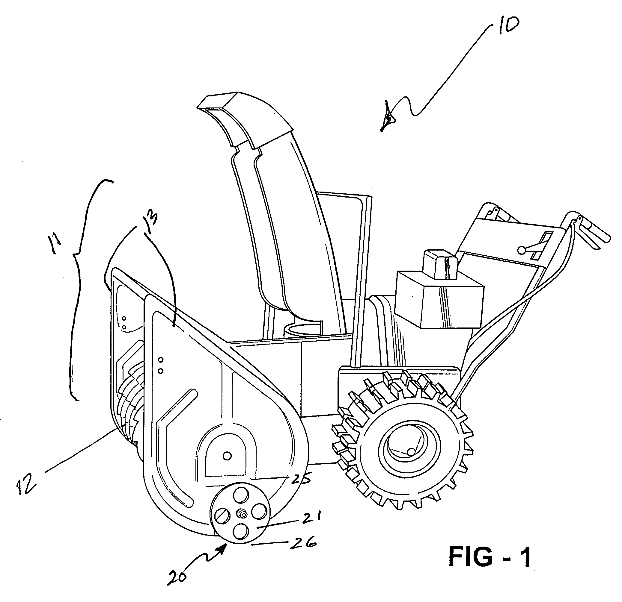
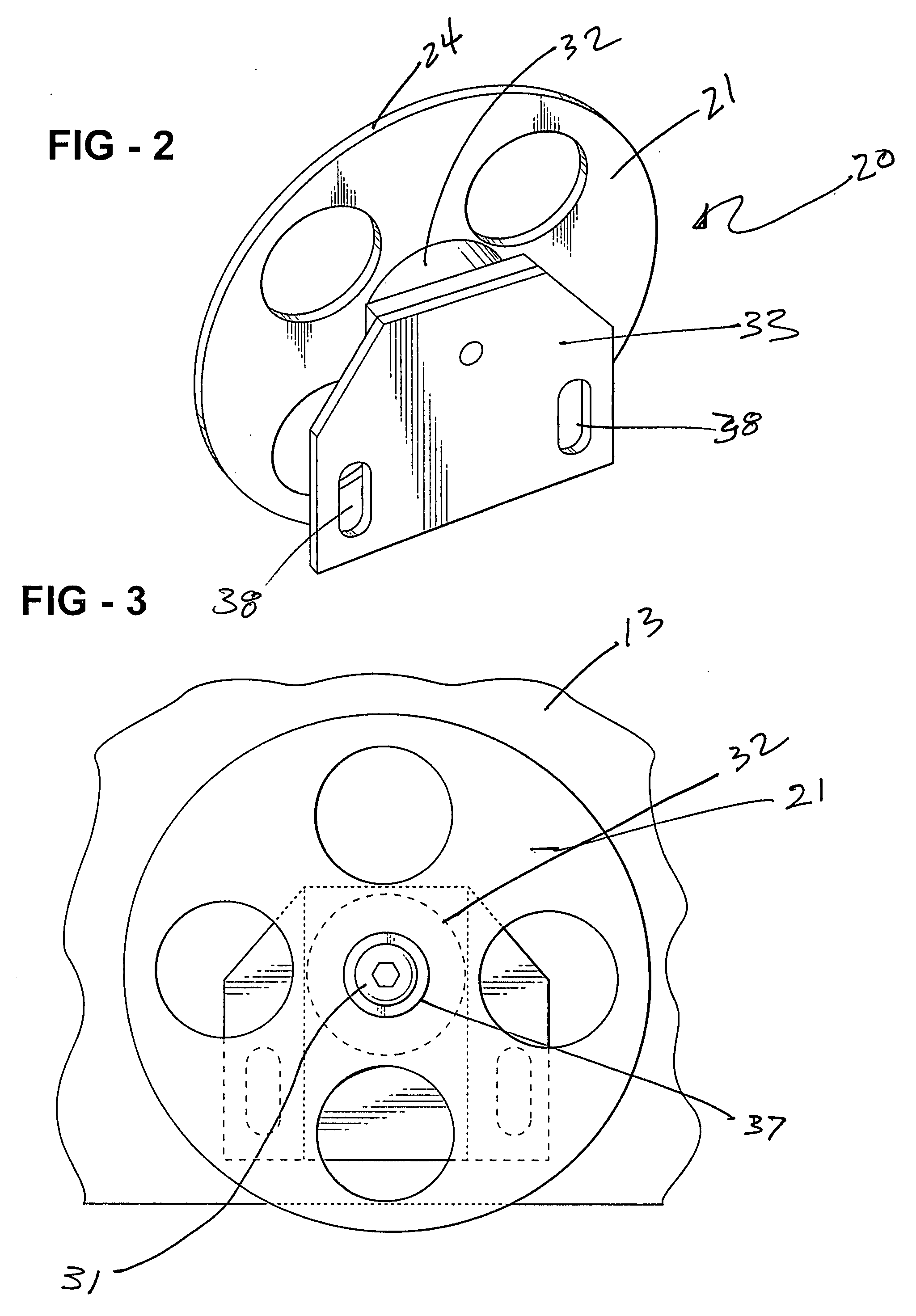
[0017]The invention Guide Disc Attachment for Snow Blower Housing, broadly considered, is a guide and weight support attachment 20 for a snow blower machine 10 having a forward snow gathering bin and auger housing assembly 11, housing a snow moving auger 12 located forward on the machine 10. The forward housing bin attachment 11 has a pair of substantially vertical sides 13, for gathering snow, each having a bottom edge 13a, and a forward cutting edge 14 extending horizontally between the bottom edges 13a of the two substantially vertical sides 13. When the snow blower machine 10 is moved forward, the lower cutting edge 14 provides a scraping function as shown in FIG. 5, and the height of cutting edge 14 above the surface to be cleared 15 defines how much, if any, snow 16, again as shown in FIG. 5, will remain on the surface after the machine has traveled over it. The instant invention 20 includes a rigid, planar disc member 21 which is constructed out of rigid material, which may b...


PUM


Abstract

A Guide Disc Attachment for Snow Blower Housing affixed in tandem to the exterior sides of a snow blower housing. Each disc is fabricated of rigid material, conformed to cut through ice and snow to an underlying hard surface and rotates on an axis parallel to the hard surface. Each disc attachment is adjustable, vertically, to regulate the distance between the underlying hard surface and the generally horizontal cutting edge of the snow blower housing. The invention allows the cutting edge to gather otherwise impacted snow and also provides lateral stability when the snow blower is moving forward.

Description

BACKGROUND OF THE INVENTION[0001]With regard to snow blowers which have a snow throwing mechanism, or auger, within a housing, which housing contacts the snow to be removed, and has a generally horizontal front or cutting edge, the concept of utilizing skid or ski plates underneath or adjacent to the sides of the housing, or wheels on the sides of the housing, to allow the housing to pass over the surface being cleared, and to adjust the height of the front or cutting edge of the housing above the surface underlying the snow to be removed, is known. Examples of prior art pertinent to this discussion include U.S. Pat. No. 4,255,879, to Greider, for a Snow Blower Deadman Control, which shows a wheel attachment (the concept of utilizing a wheel attachment to cut through the snow, or ice, to bring the snow blower assembly closer to the underlying hard surface, however, is not disclosed nor taught by the '879 patent); U.S. Pat. No. 3,913,247, to Ruhl, for an Auger and Blade Therefor Usea...

Claims


Application Information

Patent Timeline
IPC IPC(8): E01H5/09
CPCE01H5/04
Inventor LUHTANEN, JAMES L.
Owner LUHTANEN JAMES L
Why Eureka
Try Eureka