Safety Reinforced Light Transmitting Panel Assembly

a technology of light transmission panel and safety reinforcement, which is applied in the direction of door/window protection devices, building roofs, building repairs, etc., can solve the problems of increasing the risk of light transmission panel being stepped, losing the ability to support the design weight and impact, and no permanent fall protection for peopl

Active Publication Date: 2008-08-14
BLUESCOPE BUILDINGS NORTH AMERICA
View PDF23 Cites 35 Cited by
  • Summary
  • Abstract
  • Description
  • Claims
  • Application Information

AI Technical Summary

Problems solved by technology

Current light panels for metal roofing offer no permanent fall protection for people who walk on them.
However, as the material ages, it weakens and may lose the ability to support the design weights and impacts.
Additionally, years of dirt and or debris may cover the light panel and make it hard for people on the roof to distinguish the light panels from adjacent metal roof panels, thereby increasing the risk of the light panel being stepped on.
And in case of fire, the material may melt or weaken, posing a risk to a roof-borne firefighters.
However, the additional material and labor required to implement these safety features on each of the many light panels of a large building are great.

Method used


Image

  • Safety Reinforced Light Transmitting Panel Assembly
  • Safety Reinforced Light Transmitting Panel Assembly
  • Safety Reinforced Light Transmitting Panel Assembly

Examples


second embodiment

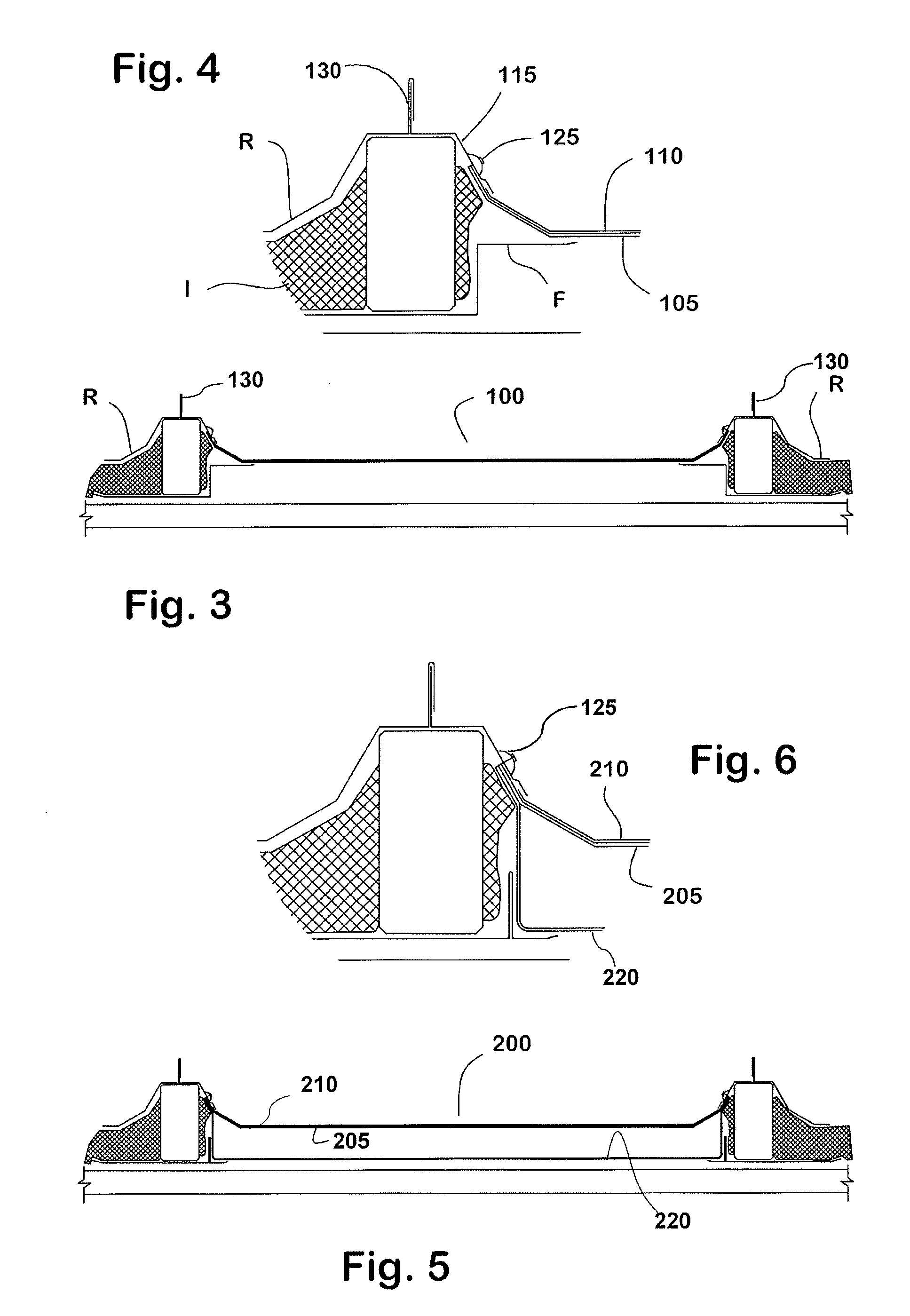
[0037]In the invention, illustrated in FIGS. 5 and 6, the roof panel assembly 200 includes a reinforcing panel 205 nested below a light-transmitting panel 210.

[0038]In this embodiment, however, there is an additional transparent polymeric panel 220 which has a trough shape so that a substantial volume of air is trapped between the upper and lower panels 210, 220.

third embodiment

[0039]FIG. 7 shows a third embodiment, in which the reinforcing panel 305 has ribs 340, 345 which act as substitutes for the trim flashing F in confining and concealing the insulation. The adjacent ribs 340, 345 together define a channel which reinforces the panel against lengthwise bending, making it not only strong enough to withstand reasonably expected or prescribed loads and impacts throughout the prescribed temperature range. The inner rib 340 confines the edge of the insulation “I” to provide a pleasing look, which the outer rib 345 bites into or compresses the insulation to keep it in place. This compression also discourages moisture from entering and degrading the insulation. If desired, an adhesive (not shown) may be used to connect the insulation facing to the rib 340.

fourth embodiment

[0040]the invention is shown in FIGS. 9 and 10. Here, a second light-transmitting panel 460 is placed between the transparent panel 410 and the reinforcing panel 405. The second light-transmitting panel 460 is constructed of any substantially transparent material, possibly the same material as the light-transmitting panel 410. In FIG. 10, the lower panel 460 is shown resting on the reinforcing panel 405, but other arrangements are possible. The plural transparent panels capture a pocket of dead air, insulating the building interior from exterior temperatures. The pocket also reduces condensation and deposits that would otherwise form following condensation on the light-transmitting panel, thus maintaining good light transmission.

[0041]A fifth embodiment of the invention is shown in FIGS. 13-14. The fifth embodiment is like the embodiment disclosed in FIGS. 9-10 in that a second light-transmitting panel 560 is placed between the transparent panel 510 and the reinforcing panel 505. Th...


PUM


Abstract

A light-transmitting roof panel assembly, having the same shape as adjoining metal roof panels in a standing seam metal roof, includes an outer transparent panel made of a polymeric material and an inner reinforcing panel made of perforated metal. The inner and outer panels nest together and lie flush with the roof. Crimpable side corrugation pieces are attached to the reinforcing panel so that the assembly can be connected to neighboring roof panels by seaming.

Description

CROSS-REFERENCE TO RELATED APPLICATIONS[0001]This application is a continuation-in-part of and claims the benefit of U.S. patent application Ser. No. 11 / 577,168 filed Apr. 12, 2007 which is a U.S. National Phase Application of PCT / US06 / 026628, filed Jul. 7, 2006, which claims the priority to U.S. Provisional Patent Application No. 60 / 699,391 filed Jul. 15, 2005, the disclosures of each being incorporated herein by reference.BACKGROUND OF THE INVENTION[0002]Industrial buildings often have skylights to provide natural lighting and to conserve energy. For buildings with metal roof systems, skylights or “light panels” may be provided in the roof system. The light panels typically have a clear or translucent sheet material formed into a shape similar to the shape of the structural metal panels of the roof, and metal sides for seaming into a standing seam type metal roof system. The light panels are lapped and sealed to the metal roof panels to provide weather-tight joints. An example of ...

Claims


Application Information

Patent Timeline
Patent Type & Authority Applications(United States)
IPC IPC(8): E04B7/18
CPCE04D3/28E04D3/364E04D3/357
Inventor MCCLURE, RICHARD R.
Owner BLUESCOPE BUILDINGS NORTH AMERICA
Why Eureka
Try Eureka