

Methods and apparatus to visualize locations of radio frequency identification (RFID) tagged items
a radio frequency identification and location technology, applied in the field of radio frequency identification systems, can solve the problems of time waste searching for a particular item or product unit, active rfid tags are typically more expensive than their passive counterparts, and active rfid tags have a much greater read range than passive tags
- Summary
- Abstract
- Description
- Claims
- Application Information
AI Technical Summary
Benefits of technology
Problems solved by technology
Method used
Image

Examples
Embodiment Construction
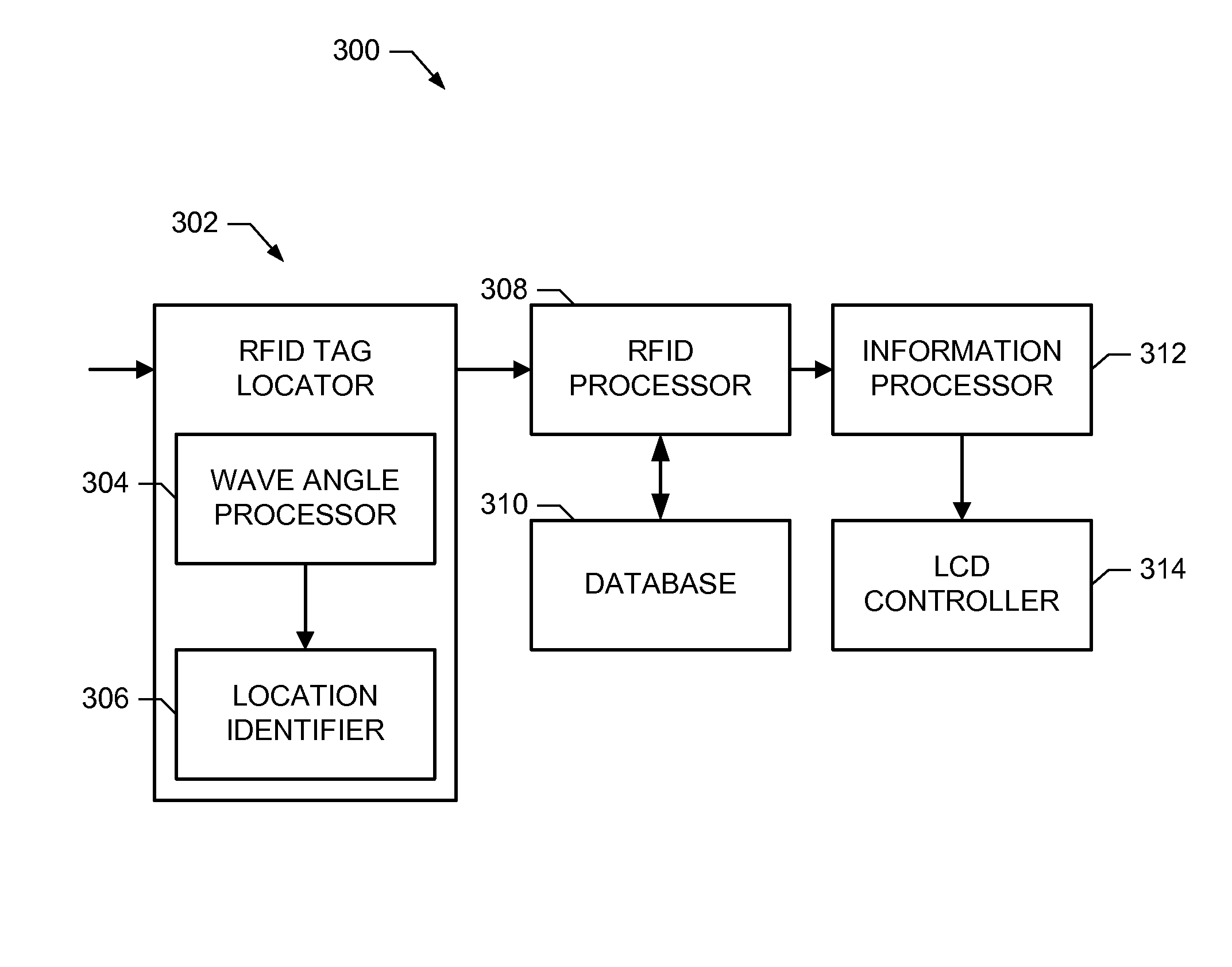
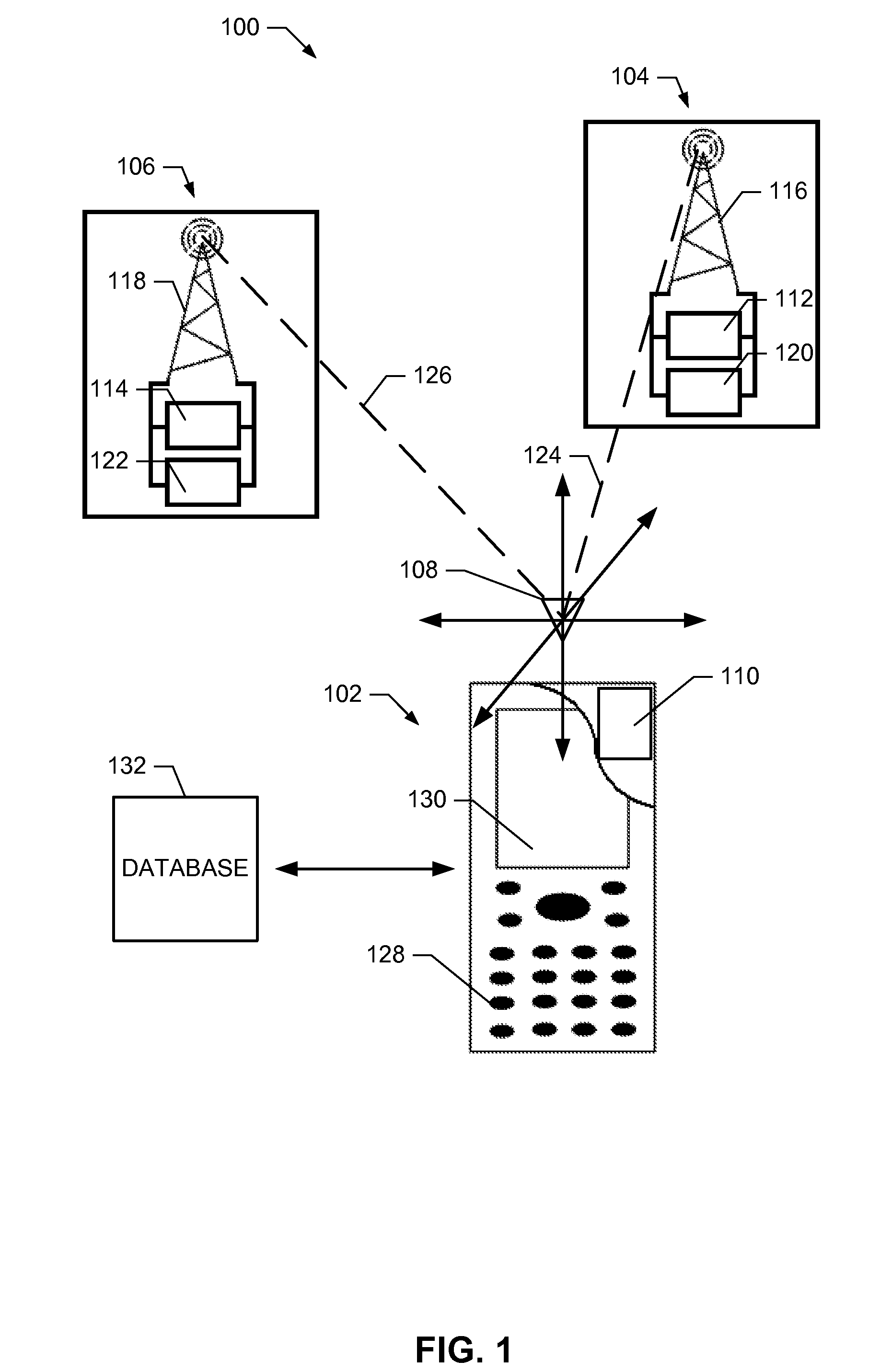
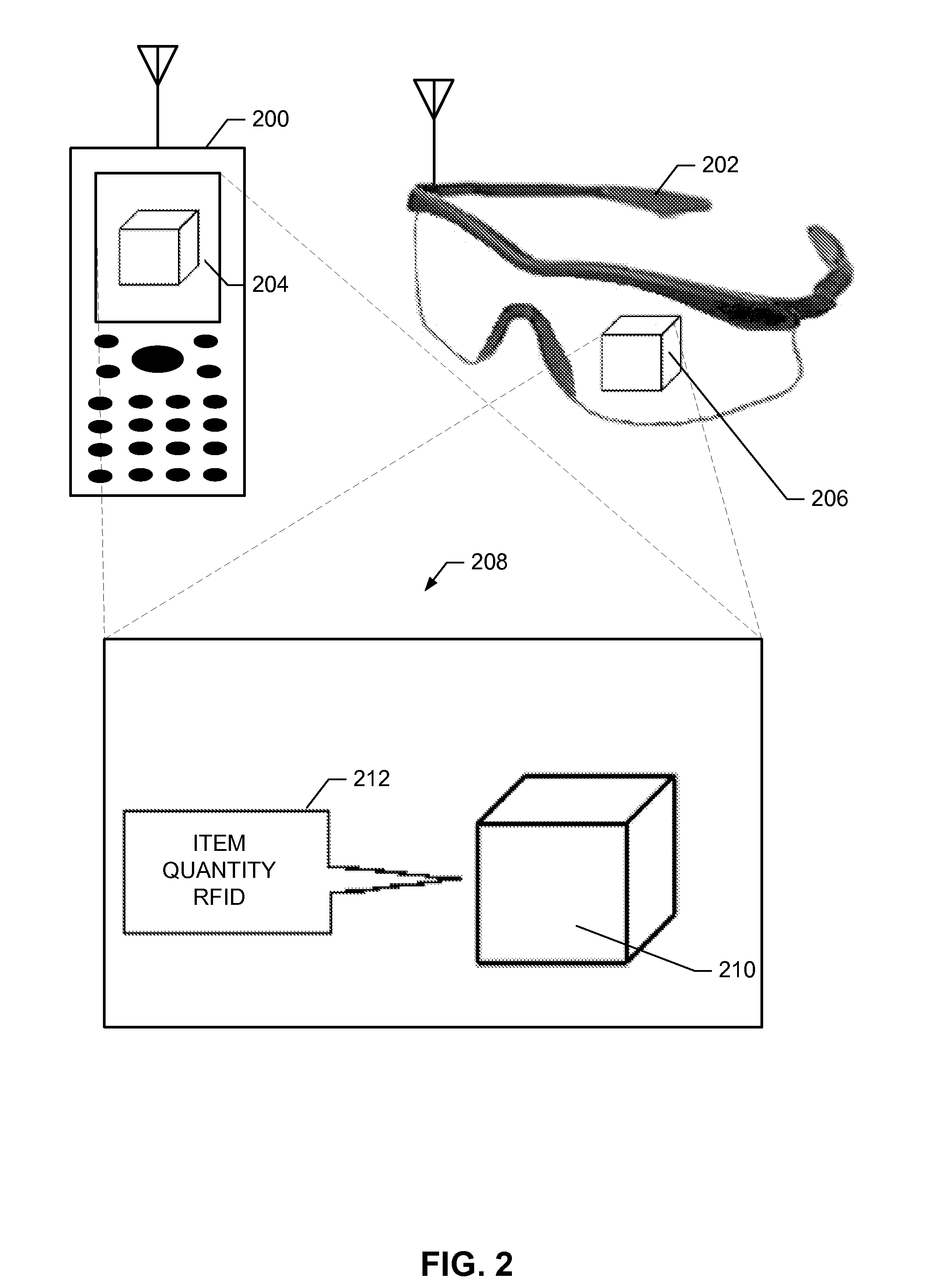
[0010]The example system discussed herein expands current RFID technology. The described RFID system increases the accuracy and ease of locating RFID tagged items and combines visual information to provide a user with a visual representation of located products items and / or information associated with the RFID tagged items. In one example, the location of the RFID tag is determined at a portable electronic device by calculating a distance and lateral position by processing RF waves and, in one particular example, the angles at which the RF waves are received. In additional examples, the system includes a portable electronic device, such as, for example, a pair of goggles or a handheld device, including a transparent display to view the RFID item. The transparent display allows the user to view the background area surrounding the item while viewing product information associated with an RFID tagged item, wherein the associated information is retrieved from a database having entries a...
PUM
 Abstract
Description
Claims
Application Information