
Livebreak fuse removal assembly for deadfront electrical apparatus

a technology for dead-front electrical equipment and fuse removal, which is applied in the direction of substations, basic electric elements, non-enclosed substations, etc., can solve the problems of difficult disconnection of fuses under electrical load for high-voltage switchgear,

Inactive Publication Date: 2008-08-14
COOPER TECH CO
View PDF99 Cites 9 Cited by
  • Summary
  • Abstract
  • Description
  • Claims
  • Application Information

AI Technical Summary

Problems solved by technology

Disconnecting fuses under electrical load for high voltage switchgear, however, is difficult.

Method used


Image

  • Livebreak fuse removal assembly for deadfront electrical apparatus
  • Livebreak fuse removal assembly for deadfront electrical apparatus
  • Livebreak fuse removal assembly for deadfront electrical apparatus

Examples


Embodiment Construction

[0013]Embodiments of a livebreak fuse removal assembly and system are provided that aids in overcoming large extraction forces for removal of fuses under electrical load at high voltages are provided. The livebreak fuse removal assembly provides deadfront protection for encapsulated fuses coupled to, for example, molded switchgear.

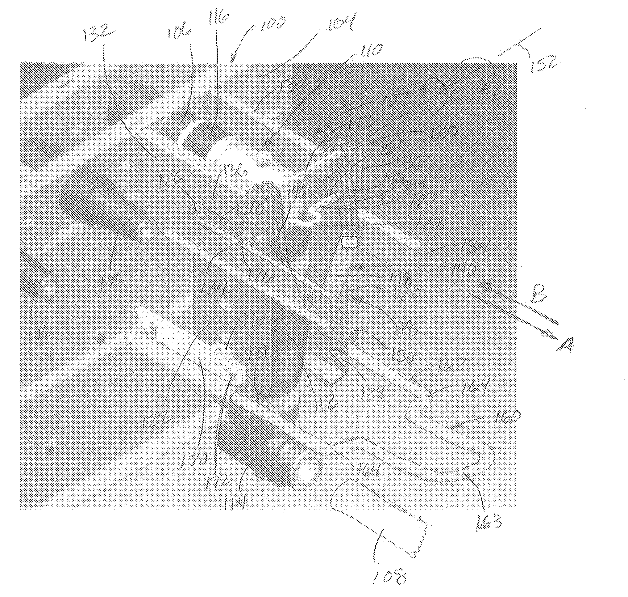
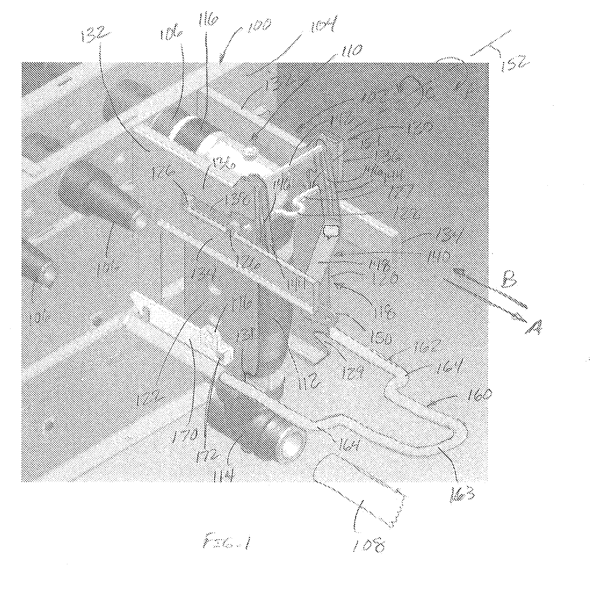
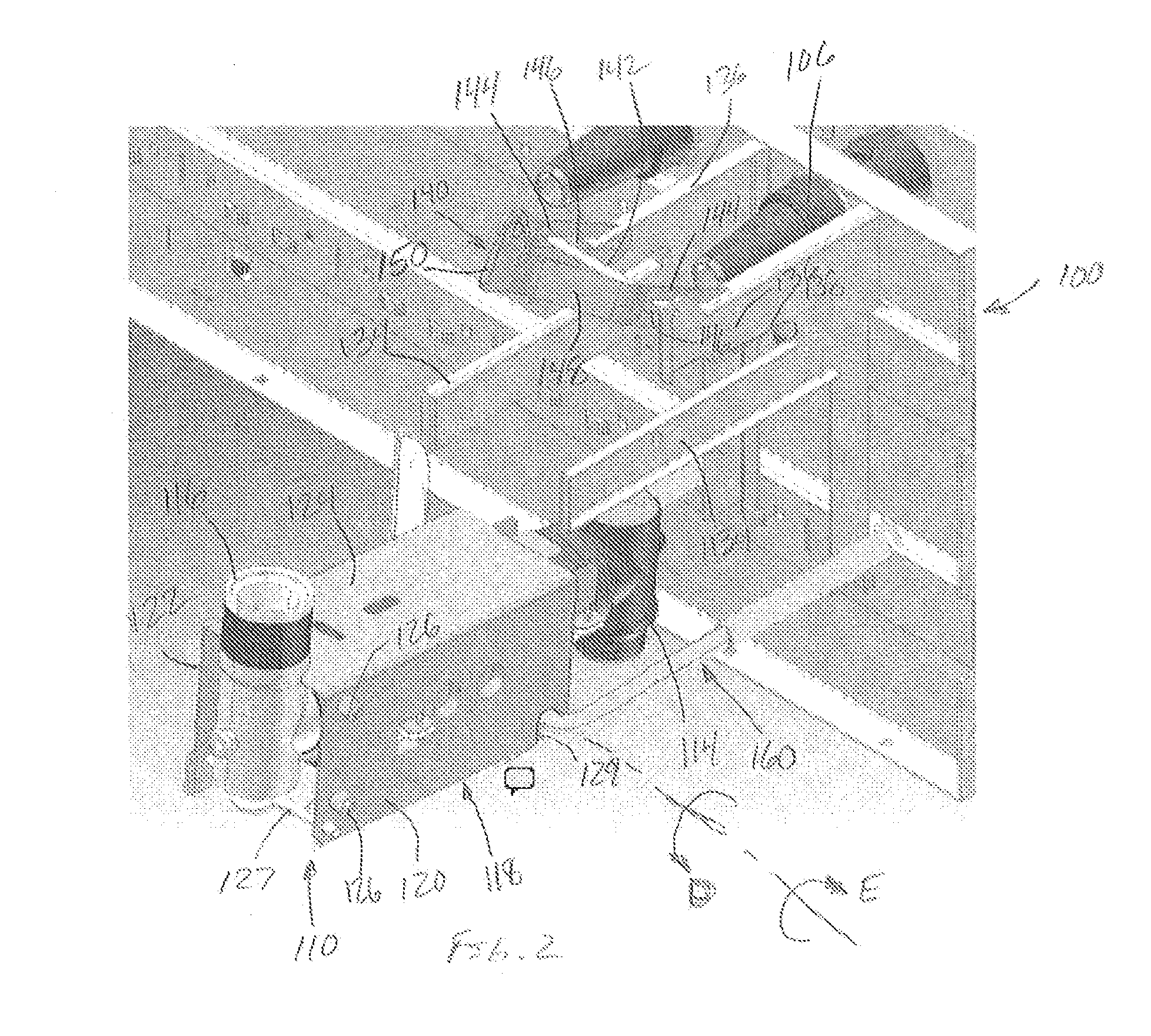
[0014]FIG. 1 is a partial perspective view of a deadfront electrical apparatus 100 including a livebreak fuse removal assembly 102. The fuse removal assembly 102 is selectively positionable between a closed position as shown in FIG. 1, and an open position shown in FIG. 2.

[0015]The electrical apparatus 100 in an exemplary embodiment may be a high voltage (e.g. 5 kV-38 kV) switchgear equipment used to distribute and control electrical power distribution, although it is appreciated that the apparatus 100 may be another type of electrical apparatus in another embodiment while substantially benefiting from the fuse removal system 102 of the invention as explai...


PUM


Abstract

Assemblies for livebreak removal of fuse assemblies for deadfront electrical apparatus such as switchgear.

Description

BACKGROUND OF THE INVENTION[0001]This invention relates generally to deadfront electrical apparatus and equipment, and more particularly to interfacing a deadfront electrical apparatus and power distribution cables through protective fuses.[0002]Electrical power is typically transmitted from substations through cables which interconnect other cables and electrical apparatus in a power distribution network. The cables are typically terminated on bushings that may pass through walls of metal encased equipment and apparatus such as capacitors, transformers or switchgear.[0003]Deadfront electrical apparatus is increasingly being used in lieu of livefront apparatus. A deadfront apparatus, as opposed to livefront apparatus, has no exposed voltage on the exterior of the apparatus and therefore provides increased, safety for both the apparatus operator and the public. The deadfront system also provides easy and efficient operation of the apparatus with a one or two man crew, for example, an...

Claims


Application Information

Patent Timeline
IPC IPC(8): H02B7/00
CPCH01H9/102H01H85/22H01H85/0208
Inventor ROSCIZEWSKI, PAUL MICHAELCAHILL, THOMAS JOSEPHMYERS, TIMOTHY ALLAN
Owner COOPER TECH CO
Learn More