Vacuum switchgear assembly, system and method

a switchgear and vacuum technology, applied in the direction of air-break switch, high-tension/heavy-dress switch, contact mechanism, etc., can solve the problems of material expansion at different rates, bottle or casting can still experience breakage, and thermal stress as the material contracts at different rates

Active Publication Date: 2007-05-17
EATON INTELLIGENT POWER LIMITED
View PDF19 Cites 56 Cited by
  • Summary
  • Abstract
  • Description
  • Claims
  • Application Information

AI Technical Summary

Problems solved by technology

It has been found, however, that either the bottle or the casting can nonetheless experience breakage due to thermal, mechanical or electrical, stress as the device is used.
The materials used to fabricate the casting and the bottle may have different thermal coefficients of expansion, and heat generated by making (closing the contacts), breaking the circuit (opening the contacts), and interrupting fault currents can be significant, which causes the materials to expand rapidly at different rates.
Thermal contraction, when cooling after a manufacturing process such as molding, may also cause thermal stress as the materials contract at different rates.
Thermal cycling due to seasonal changes from summer to winter or a daily change from day to night may also produce thermal stress, and the cumulative effects of thermal stress may lead to fatigue and premature failure of the device.
Despite such efforts to isolate the vacuum bottle from mechanical stress, misalignment of the switch or interrupter devices can nonetheless cause the bottle and/or support structure to break due to mechanical forces associated with opening and closing of the contacts in use.
If, for example, an actuator shaft of the operating mechanism is misaligned, however slightly, with the axis of the switch or interrupter device, the bottle, and not the supporting structure for the bottle, can become subject to mechanical loads during opening and closing of the contacts.
Depending upon the severity and frequency of such loads, the structural integrity of the bottle can be compromised, and perhaps even destroyed.
Loading of the bottle due to misalignment of the bottle with respect to the operating shaft may further cause the switch or int

Method used


Image

  • Vacuum switchgear assembly, system and method
  • Vacuum switchgear assembly, system and method
  • Vacuum switchgear assembly, system and method

Examples


Embodiment Construction

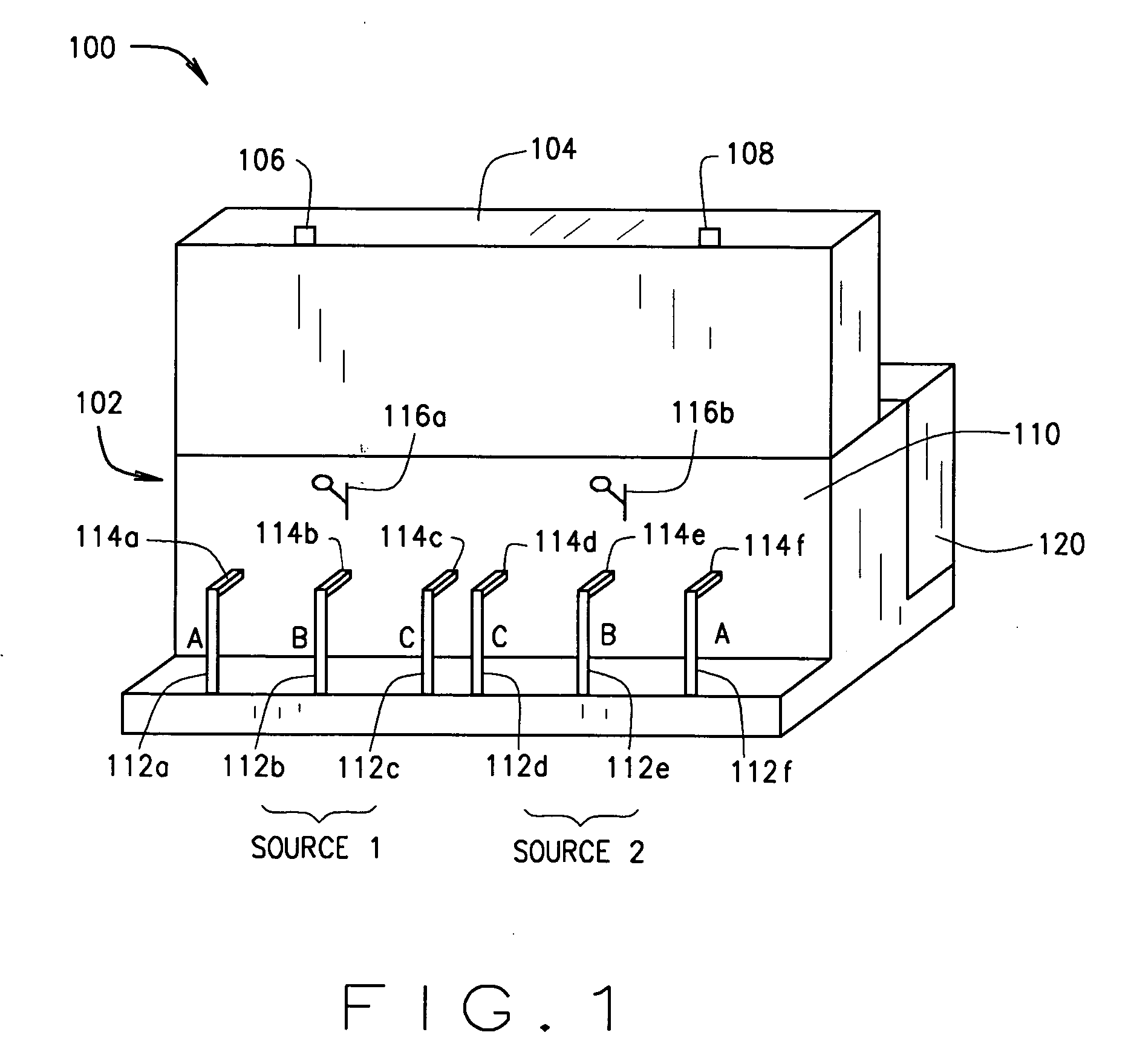
[0030]FIG. 1 illustrates an exemplary switchgear configuration 100 in which vacuum switch or interrupter assemblies according to the present invention may be used. While one exemplary switchgear 100 is described, it is understood that the benefits of the invention accrue generally to switchgear of many configurations, and that the switchgear 100 is but one potential application of the switch or interrupter assemblies described hereinbelow. Switchgear 100 is therefore illustrated and described herein for illustrative purposes only, and the invention is not intended to be limited to any particular type of switchgear configuration, such as the switchgear 100.

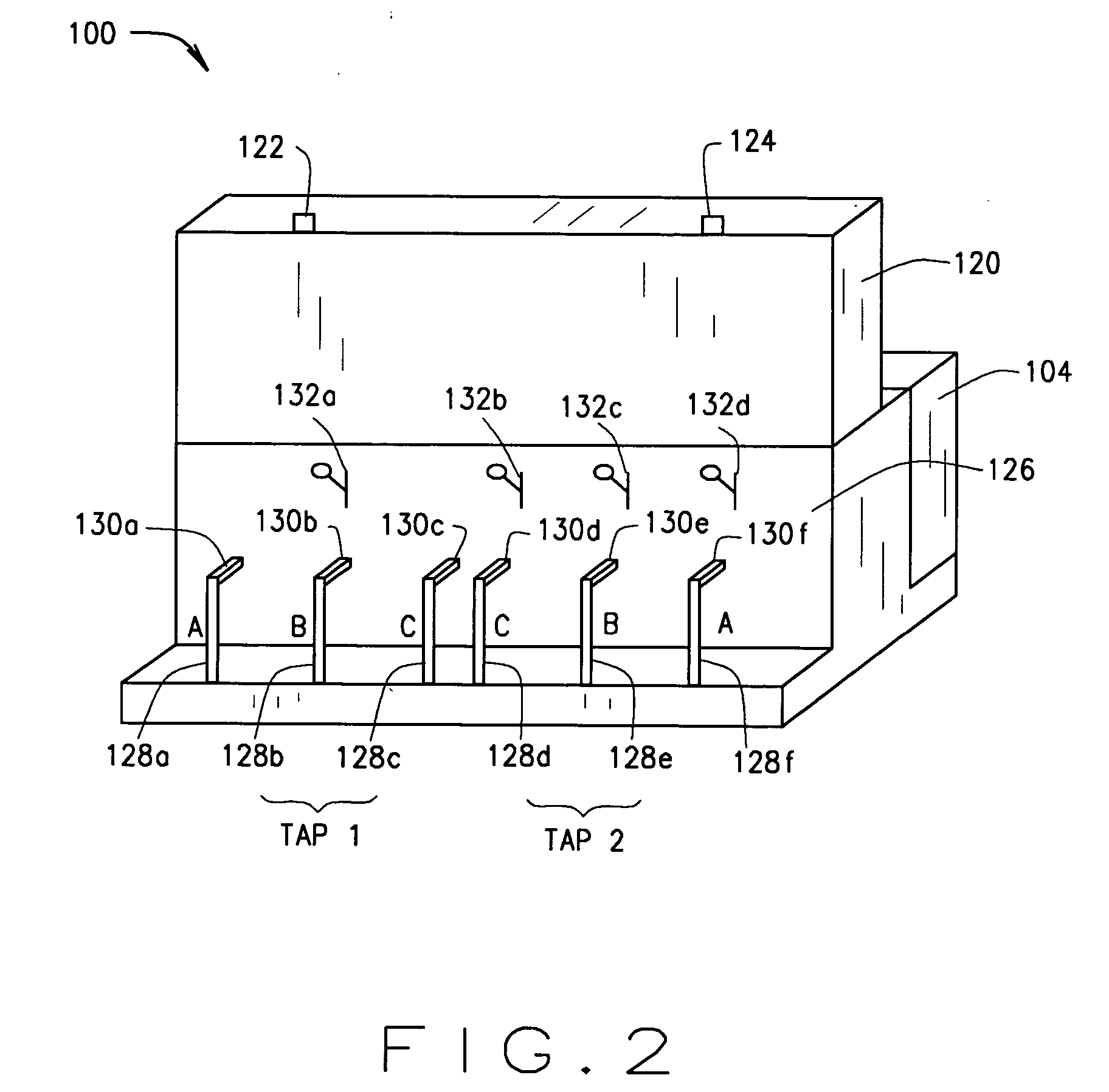
[0031] As shown in FIG. 1, the switchgear 100 includes a protective enclosure 102 having, for example, a source side door 104 positionable between an open position (FIG. 1) and a closed position (FIG. 2). Latch elements 106 and / or 108 may be used to lock source side door 104 in a closed position. Inside the source side door 104 is...


PUM

PropertyMeasurementUnit
Volumeaaaaaaaaaa
Coefficient of linear thermal expansionaaaaaaaaaa
Thermal propertiesaaaaaaaaaa

Abstract

Insulated vacuum switchgear and active switchgear elements therefor are provided with a rigid support structure mechanically isolating a vacuum insulator from axial loads in use without reinforcing or insulating encapsulations. At least one of the elastomeric insulating housing and the support structure directly contacts an outer surface of the insulator. Systems and methods for assembling the switchgear are also provided.

Description

BACKGROUND OF THE INVENTION [0001] This invention relates generally to high voltage switchgear, and more particularly, to vacuum switch or interrupter assemblies for use in such switchgear. [0002] Utility companies typically distribute power to customers using a network of cables, transformers, capacitors, overvoltage and overcurrent protective devices, switching stations and switchgear. Switchgear is high voltage (e.g. 5 kV-38 kV) equipment used to distribute and control power distribution. Padmounted or underground switchgear includes an enclosure or container that houses bushings, insulation, a bus bar system, and a collection of active switching elements. The active switching elements may include internal active components, such as a fuse, a switch, or an interrupter and external points of connection, such as bushings, to establish line and load connections to an electrical distribution system. Distribution cables transmit power at high voltages. These cables are typically coupl...

Claims


Application Information

Patent Timeline
IPC IPC(8): H01H33/66
CPCH01H33/66207H01H33/666Y10T29/49826H01H2033/6665H01H2033/6623
Inventor MUENCH, FRANK JOHNCULHANE, MICHAEL PATRICKSTEINBRECHER, BRIAN TODDSTOVING, PAUL NEWCOMBMAKAL, JOHN MITCHELLROSCIZEWSKI, PAUL MICHAEL
Owner EATON INTELLIGENT POWER LIMITED
Why Eureka
Try Eureka