Bus joint assembly

a bus and joint technology, applied in the direction of connection contact member materials, electric cable installation, coupling device connection, etc., can solve the problems of lack of horizontal support while splicing the bus, rather labor-intensive installation of the bus bar, and lack of horizontal support while the bus is fastened, etc., to achieve the effect of improving the assembly process tim

Active Publication Date: 2008-11-11
SIEMENS ENERGY & AUTOMATION INC
View PDF11 Cites 57 Cited by
  • Summary
  • Abstract
  • Description
  • Claims
  • Application Information

AI Technical Summary

Benefits of technology

[0010]The bus joint connector with fixture pins solves the assemblability issue of having to locate, align and support the horizontal bus while assembling the splice bus and hardware in the same step. The advantage of having the horizontal bus located, aligned and supported allows a single installer to focus on assembling just the splice bus and hardware. This greatly improves assembly process time.

Problems solved by technology

Installation of bus bars are rather labor intensive and require careful assembly.
A problem faced during installation is aligning and supporting the horizontal bus bars to the vertical bus bars in an efficient and expeditious manner.
A disadvantage of known main bus joint designs is the lack of horizontal support while splice buses are fastened.
This process is difficult and time consuming for a single installer.

Method used


Image

  • Bus joint assembly
  • Bus joint assembly
  • Bus joint assembly

Examples


Embodiment Construction

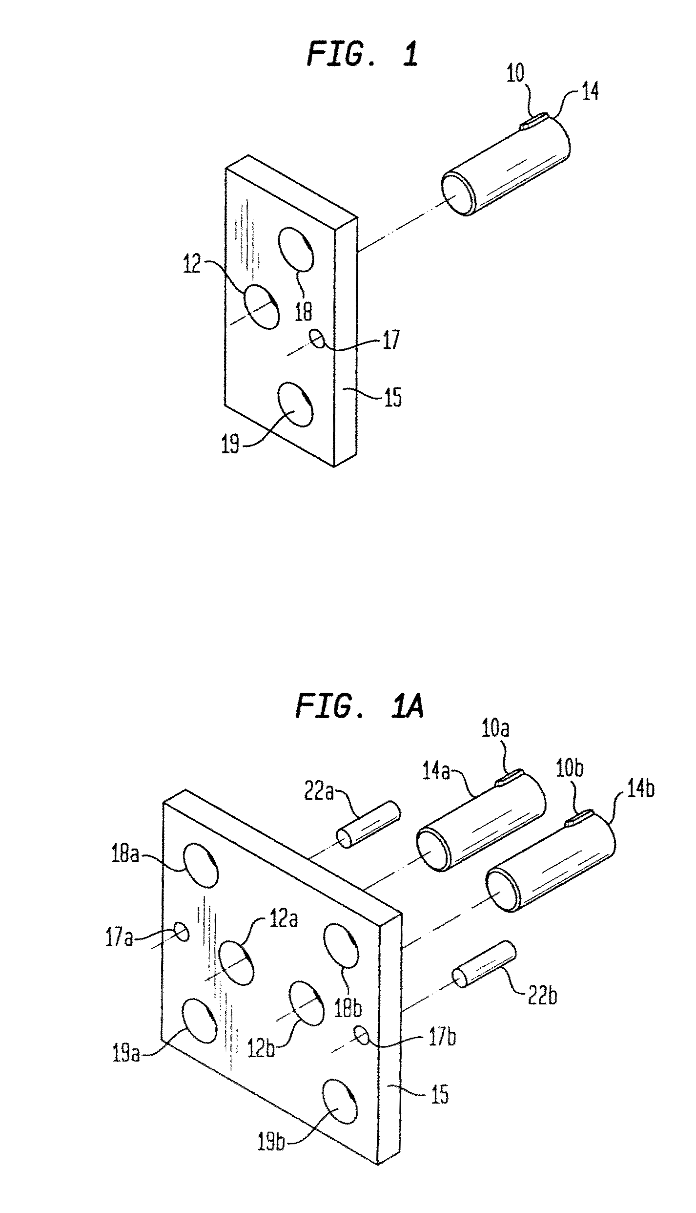
[0026]Shown in FIG. 1 is a nut plate 15 for use with the bus joint connector 24 shown in FIG. 2. The nut plate 15 is preferably made of metal such as steel although other supportive materials such as, cooper, aluminum, or an alloy may be used. Steel is an often preferred material since it is very strong and performs very well in maintaining thread integrity.

[0027]The nut plate arrangement is preferred over a single bolt-single nut design arrangement since there are fewer parts to handle, and it is easier to assemble when access is near impossible. The nut plate 15 is shown in a rectangular form for illustration purposes only. The shape of the nut plate 15 may take whatever form is most economical or structurally appropriate. For example the nut plate 15 may be made in a circular disk shaped form when stamping is used to mass produce nut plate 15.

[0028]The nut plate 15 in its preferred form comprises at least one hole 12 through which a fixture pin 14 may be engaged. As will be discu...


PUM


Abstract

A bus joint assembly for use in switchgear equipment having bus bars joined together at a bus joint and for joining vertical and horizontal buses. The bus joint connector comprises a connector, nut plate, connecting and supporting pins as well as a splice bus connector. The bus joint connector with integrated fixture pins locates and supports horizontal buses to vertical buses during assembly.

Description

CROSS REFERENCE TO RELATED APPLICATIONS[0001]This application claims priority to U.S. Provisional Patent Application No. 60 / 779,597 filed Mar. 6, 2006, entitled “Bus Joint Interface” is incorporated fully herein by reference.FIELD OF THE INVENTION[0002]The present invention relates generally to the field of electrical switchboards and panel boards having bus bars, and more specifically to a bus joint connector for facilitating the assembly of bus bars generally found in switchgear assemblies.BACKGROUND OF THE INVENTION[0003]Switchgear assemblies, switchboards and panelboards are general terms which cover metal enclosures, housing switching and interrupting devices such as fuses, and circuit breakers, along with associated control, instrumentation and metering devices. Such assemblies typically include associated bus bars, interconnections and supporting structures used for the distribution of electrical power. Low voltage switchgear and switchboards operate at voltages up to 600 vol...

Claims


Application Information

Patent Timeline
Patent Type & Authority Patents(United States)
IPC IPC(8): H02G5/00
CPCH01R4/304H01R4/307H01R4/38H01R25/162H02B1/21H01R4/5083
Inventor WIANT, JASON P.
Owner SIEMENS ENERGY & AUTOMATION INC
Why Eureka
Try Eureka