Joint assembly

a joint assembly and assembly technology, applied in the direction of sheet joining, key-type connection, fastening means, etc., can solve the problems of bolts prone to galling and seizing, thermal cycling problems, and high cost and time-consuming

a joint assembly and assembly technology, applied in the direction of sheet joining, key-type connection, fastening means, etc., can solve the problems of bolts prone to galling and seizing, thermal cycling problems, and high cost and time-consuming

US20210131466A1Pending Publication Date: 2021-05-06ROLLS ROYCE PLC

Image

  • Joint assembly
  • Joint assembly
  • Joint assembly

Examples


Embodiment Construction

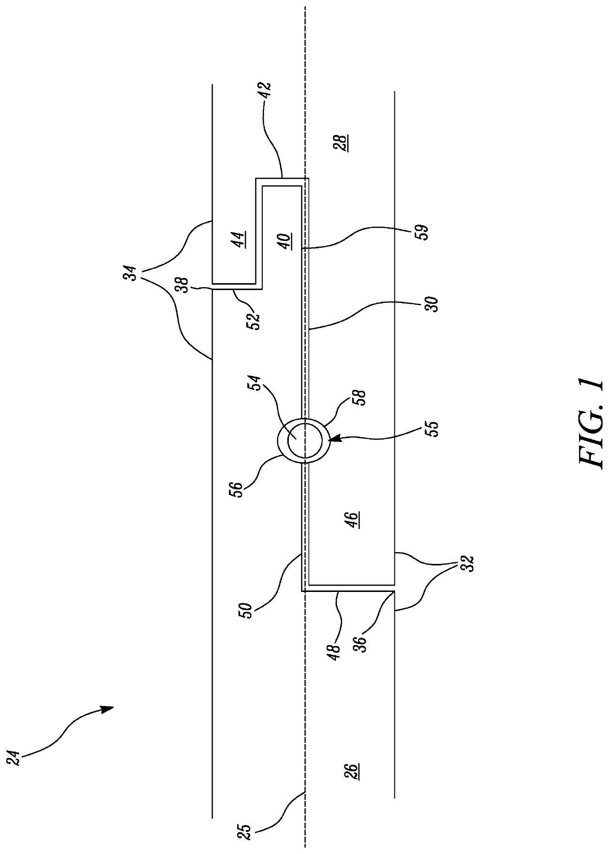
[0029]FIG. 1 shows a sectional view through a joint assembly 24 according to a first example of the disclosure.

[0030]The joint assembly 24 comprises a first member 26 and a second member 28, joined together at an interface 30 located between opposing surfaces of the first and second member. The joint assembly 24 is configured to unite the first and second member to provide a releasable or permanent connection therebetween.

[0031]In this example, the first 26 and second 28 members are annular in form and the joint assembly 24 is for a revolute component. Both the first and second members are hollow. In other examples, only the first member 26, or an end portion thereof, need be hollow and the second member 28 could have a solid interior. Furthermore, the first 26 and second 28 members need not be circular in cross-section and could be elliptical or polygonal in different examples.

[0032]It will be appreciated that only one half of the joint section is shown in the examples herein, i.e....


PUM


Abstract

A joint assembly joins first and second components about a common axis. The first component has a first end portion having a radially outwardly facing surface shaped to fit radially inside a second surface of a hollow second end portion of the second component to form an interface between the opposing first and second surfaces. The first and second surfaces have a concavity extending laterally with respect to the axis such that when the first and second surfaces are opposingly arranged the opposing concavities define a cavity at the interface. A retaining member is insertable into the cavity at the interface to prevent axial separation of the first and second components. One of the first and second end portions has a free end protrusion axially spaced from the concavity and the other of the first and second end portions has an axially extending recess arranged to receive the free end.

Description

[0001]This specification is based upon and claims the benefit of priority from UK Patent Application Number GB 1915814.6 filed on 31 Oct. 2019, the entire contents of which are incorporated herein by reference.BACKGROUNDOverview of the Disclosure[0002]The present disclosure relates to a joint assembly, particularly to a joint assembly for locking two components together.Background of the Disclosure[0003]Most gas turbine engines employ conventional nut and bolt configurations to secure together the main structural engine components, such as fan and body casing parts. The temperature of gases passing through the engine can range between approximately 700° and approximately 2500° C. which can cause thermal cycling problems. As the engine temperature varies through such a temperature range, bolts tend to gall and seize. This can require the bolts to be drilled out during the disassembly of the engine, which is expensive and time-consuming.[0004]In addition, the use of nuts and bolts req...

Claims


Application Information

Patent Timeline
06 May 2021
Publication
US20210131466A1
IPC
F16B5/00
CPC
F16B5/0088; F05D2260/30; F05D2260/36; F16B3/04; F01D25/243; F16B5/0012; F16B5/0044; F16B7/0406
Inventors
COLES, DAVID R; CLARK, DANIEL