Multi-access Switchgear Assembly

a switchgear and multi-access technology, applied in the field of electrical enclosures, can solve the problems of significant economic loss, large space occupation of switchgear cabinets for medium voltage equipment, and damage to switchgear cabinets, especially medium voltage metal clad switchgear cabinets,

Active Publication Date: 2011-12-08
IEM HLDG GRP INC
View PDF6 Cites 55 Cited by
  • Summary
  • Abstract
  • Description
  • Claims
  • Application Information

AI Technical Summary

Problems solved by technology

The switchgear cabinet for medium voltage equipment typically occupies a large space and is difficult to access.
Switchgear cabinets, particularly medium voltage metal clad switchgear cabinets are often damaged due to arcing.
An explosion caused by arcing within a switchgear cabinet results in significant economic loss due to interruption of energy distribution, and damage of the switchgear cabinet and the electrical components or equipment accommodated in the switchgear cabinet.
Consequently, maintenance personnel inspecting and servicing the switchgear cabinets have to wear protective gear that is bulky and expensive.
Typical arc resistant switchgear cabinets tend to be very large and often have heavy sheet metal enclosures.
Such configurations require significant space.
Therefore, single access switchgear cabinets do not make an efficient use of the available floor space owing to the lesser flexibility available in positioning the electrical components and the electrical cables within the switchgear cabinet.
Moreover, conventional single access switchgear cabinets do not allow accommodation of multiple electrical components along with electrical cables in a single section.
Furthermore, conventional switchgear cabinets utilize bar type current trans...

Method used


Image

  • Multi-access Switchgear Assembly
  • Multi-access Switchgear Assembly
  • Multi-access Switchgear Assembly

Examples


Embodiment Construction

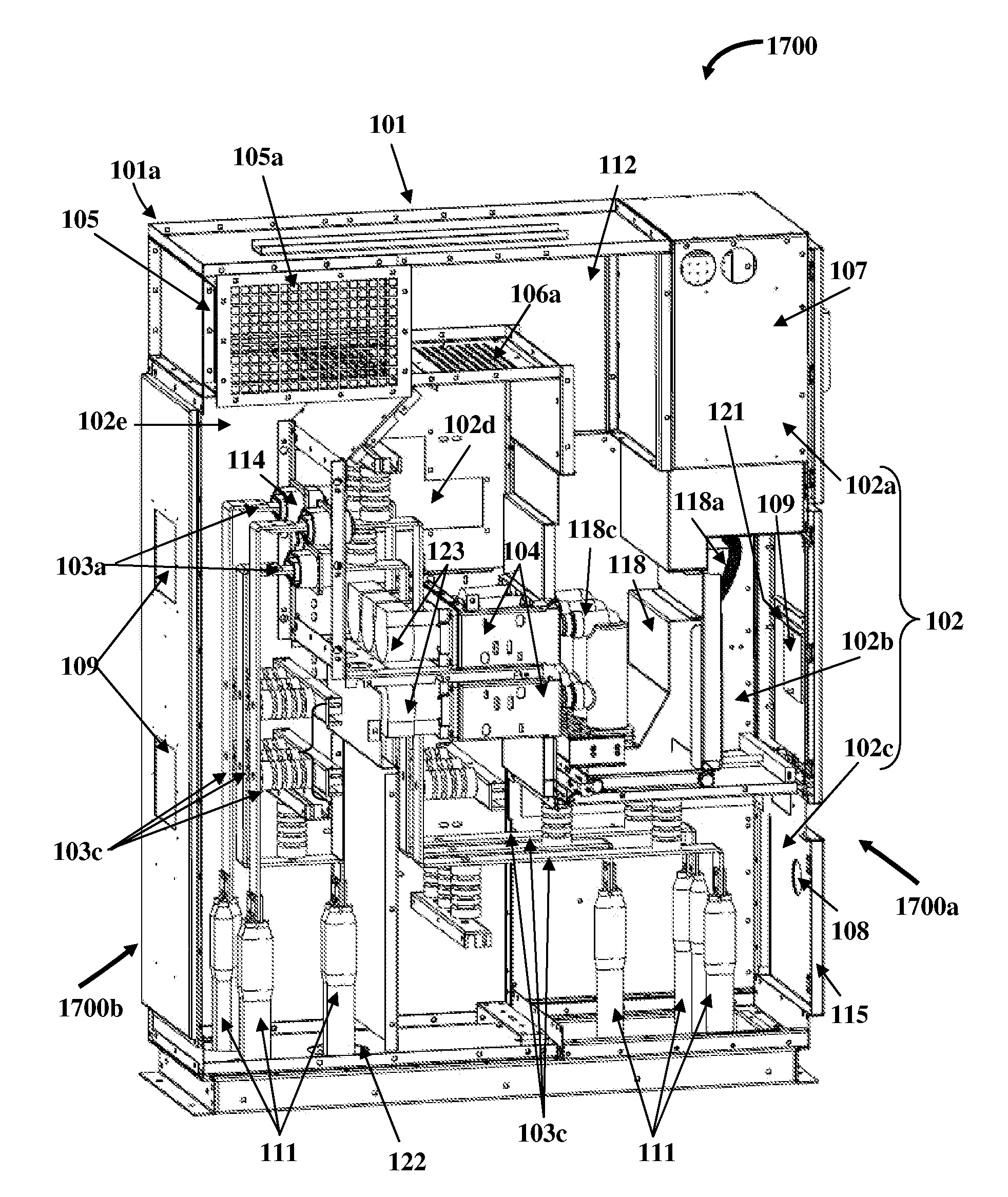
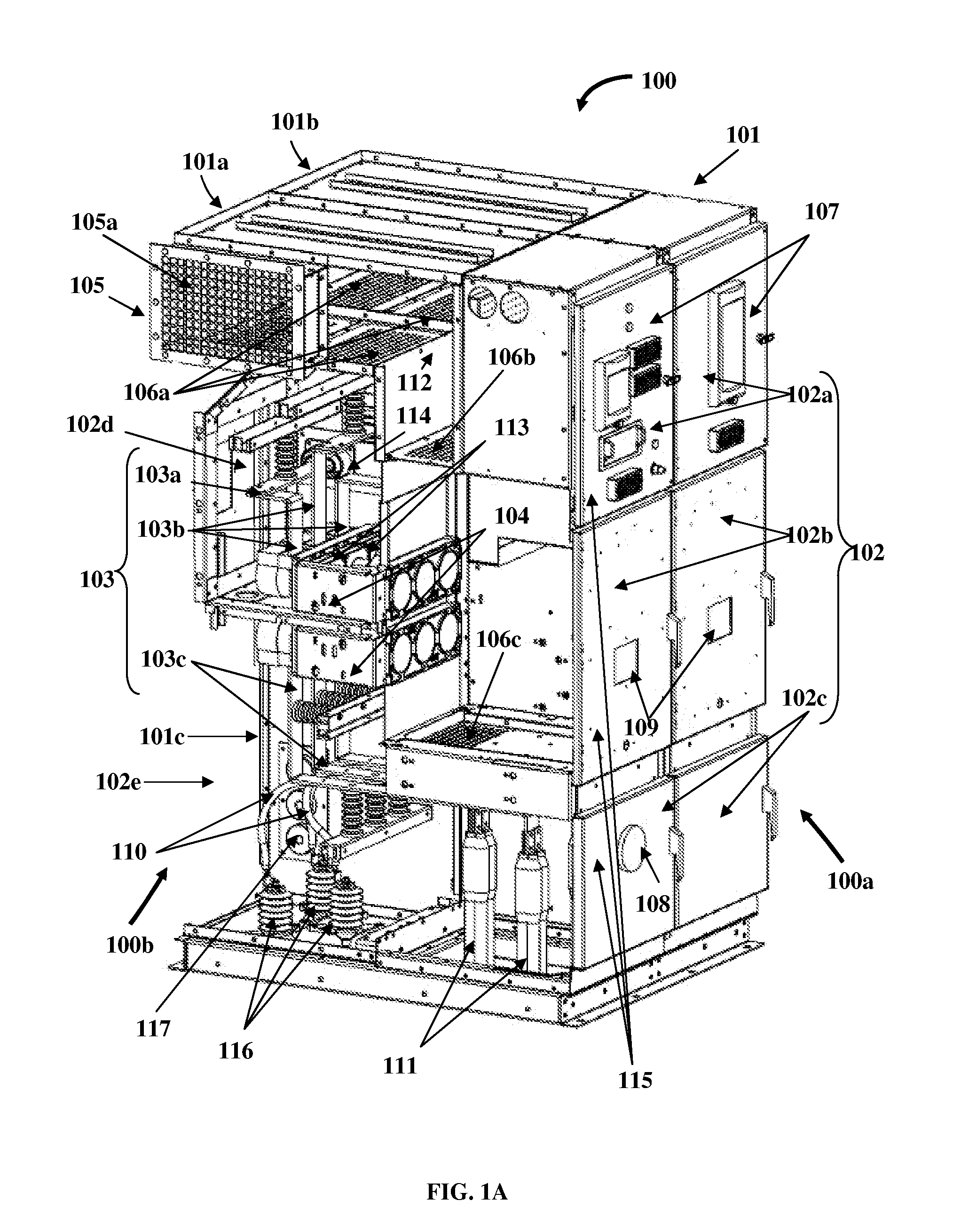
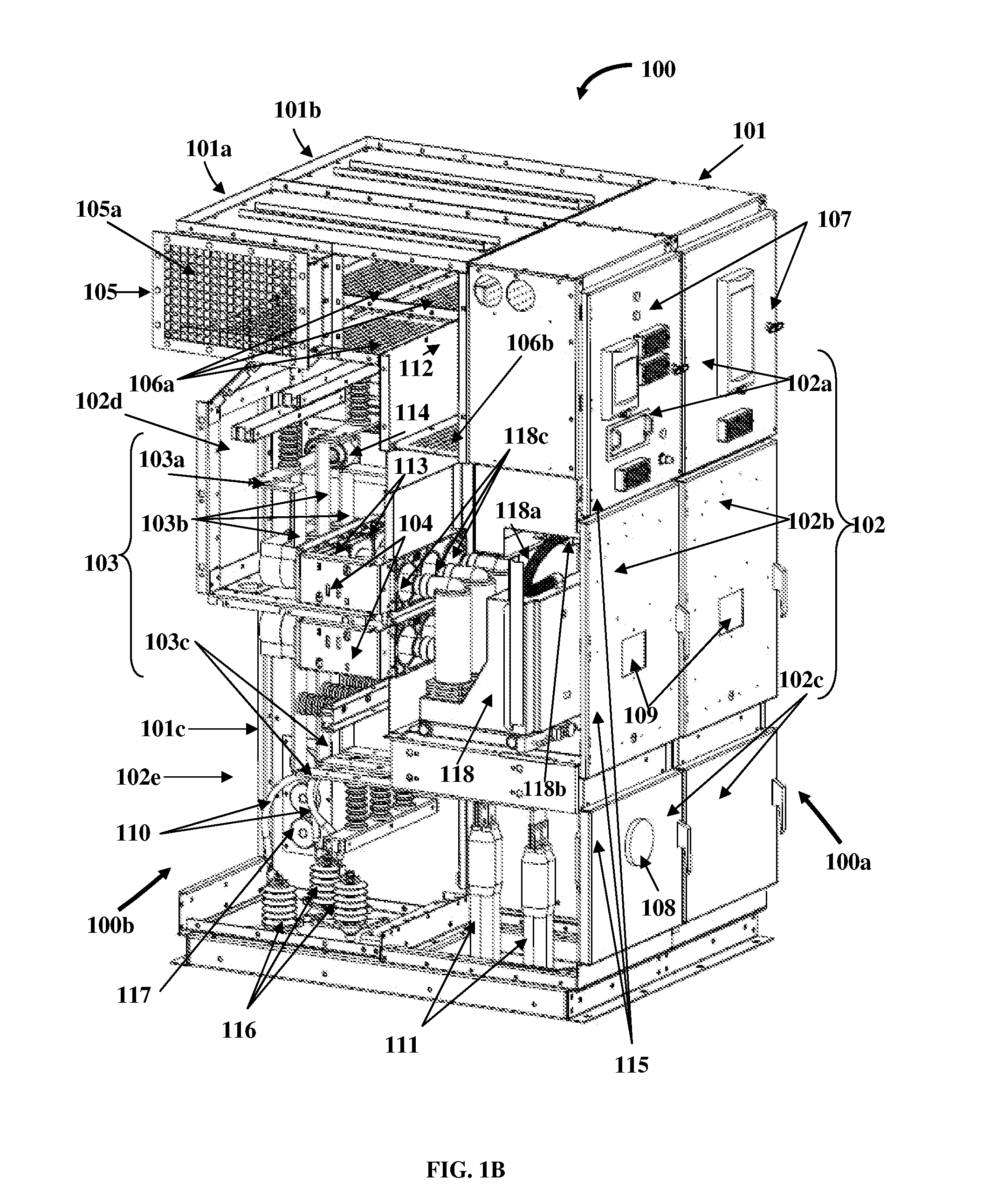
[0068]Disclosed herein is a compact arc resistant metal clad switchgear assembly that has a compact footprint and provides either front access only, or front access and rear access herein referred to as “multi-access”, to electrical components, electrical cables, equipment, etc., accommodated in the switchgear assembly for inspection, testing and maintenance with limited space requirements and without protective gear. The compact arc resistant metal clad switchgear assembly that provides front access only is herein referred to as a “front accessible switchgear assembly”. As used herein, the front accessible switchgear assembly 100, exemplarily illustrated in FIGS. 1A-16D, refers to a switchgear assembly 100 that allows access to electrical cables 111, electrical components 113, 118, 119, 120, etc., the bus bars 103, and equipment accommodated within the switchgear assembly 100 from the front side 100a of the switchgear assembly 100 only. The compact arc resistant metal clad switchge...


PUM

PropertyMeasurementUnit
Currentaaaaaaaaaa
Currentaaaaaaaaaa
Temperatureaaaaaaaaaa

Abstract

A metal clad switchgear assembly comprising multiple compartments defined within an electrical enclosure is provided. The compartments interchangeably accommodate electrical components, for example, current transformers, a circuit breaker, a control power transformer, an epoxy encapsulated potential transformer, etc., electrical cables, and bus bars in predetermined positions for allowing front access and/or rear access to them. One or more compartments are configured for enabling the electrical cables to enter into and/or exit out from the electrical enclosure for allowing front and/or rear access to the electrical cables. A mounting block assembly is positioned in one or more of the compartments for mounting, enclosing, and providing front access to the electrical components. One or more infrared windows and inspection windows are positioned on a front side and/or a rear side of the switchgear assembly for scanning and providing a visual indication of the electrical components, the electrical cables, and the bus bars.

Description

CROSS REFERENCE TO RELATED APPLICATIONS[0001]This application is a continuation-in-part application of non-provisional patent application Ser. No. 12 / 905,077 titled “Front Accessible Switchgear Assembly”, filed on Oct. 14, 2010 in the United States Patent and Trademark Office, and claims the benefit of provisional patent application No. 61 / 352,022 titled “Multi-access Switchgear Assembly”, filed on Jun. 7, 2010 in the United States Patent and Trademark Office.[0002]The specifications of the above referenced patent applications are incorporated herein by reference in their entirety.BACKGROUND[0003]The apparatus disclosed herein, in general, relates to electrical enclosures. More particularly, the apparatus disclosed herein relates to electrical enclosures that provide, for example, front access only, and front and rear access herein referred to a “multi-access”, to electrical bus members, multiple electrical components, and apparatuses housed within the electrical enclosures. Further...

Claims


Application Information

Patent Timeline
IPC IPC(8): H02B13/02H01R43/00
CPCH02B1/21H02B11/26Y10T29/49117H02B13/0356H02B13/02H02B11/04
Inventor MILOVAC, PREDRAGKULKARNI, ASHOK BABURAOROSSI, EDWARD JOSEPHSAPP, DENNIS WAYNE
Owner IEM HLDG GRP INC
Why Eureka
Try Eureka