Tampon Applicator Assembly

a technology of applicator and assembly, which is applied in the field of tampon applicator assembly, can solve the problems of assembly with displaced tampons that cannot be used and need to be discarded, consumer annoyance, and displacement of tampons, so as to reduce the total amount of contact, reduce the overall friction, and advantageously minimize the likelihood of tampon displacement

Active Publication Date: 2008-08-14
ONTEX HIGIENEARTIKEL DEUT GMBH
View PDF98 Cites 22 Cited by
  • Summary
  • Abstract
  • Description
  • Claims
  • Application Information

AI Technical Summary

Benefits of technology

[0009]Such areas of radial depression are defined by a smaller radius on transverse cross-section than adjacent areas of the outer surface of the tampon and therefore will be radially spaced away from the structures of the applicator which may contact the outer surface of the tampon during use of the assembly, i.e., during cocking and ejection steps. Such structures may particularly include the inner surface of the ejector tube and the surface and edges of the fingers of the ejector tube and of the petal sections of the outer tube. Consequently, the areas of radial depression will not contact the respective structures of the applicator during use of the assembly. This will reduce the total amount of contact between the outer surface of the tampon and the respective structures of the applicator during use. Reduction of contact between the outer surface of the tampon and the inner surface and fingers of the ejector tube may decrease the overall friction and therefore advantageously minimizes the likelihood of displacement of the tampon in the proximal direction during the cocking step, and facilitates easier withdrawal of the ejector tube during the cocking step. Further, reduction of contact between the outer surface of the tampon and the inner surface and / or edges of the fingers and of the petal sections may decrease the overall friction and therefore advantageously minimize disruption of the tampon surface by said structures and loss of tampon material displaced by said fingers or petal sections during cocking and ejection steps.

Problems solved by technology

Nevertheless, when the ejector tube is being withdrawn, the close association between the outer surface of the tampon and the opposing inner surface of the ejector tube may occasionally override this engagement, leading to displacement of the tampon.
Because the hygienic requirements preclude further manipulation of the assembly by the user to reposition the tampon, assemblies with displaced tampons are unusable and need to be discarded.
Hence, a small proportion of presently existing assemblies malfunctions and must be discarded, which may lead to consumer annoyance especially in situations when no other assemblies are at hand.
Therefore, the surface or the edges of these fingers may occasionally scrape material from the outer surface of the tampon, leading to undesirable loss of material.
Hence, the surface or edges of the petal sections may also retain material from the outer surface of the tampon, leading to further unwanted loss of material.

Method used


Image

  • Tampon Applicator Assembly
  • Tampon Applicator Assembly
  • Tampon Applicator Assembly

Examples


Embodiment Construction

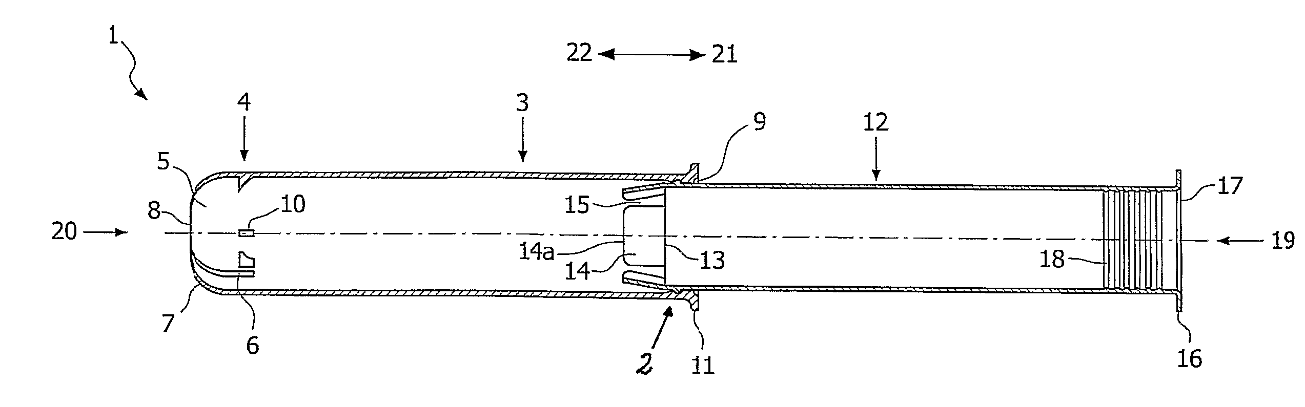
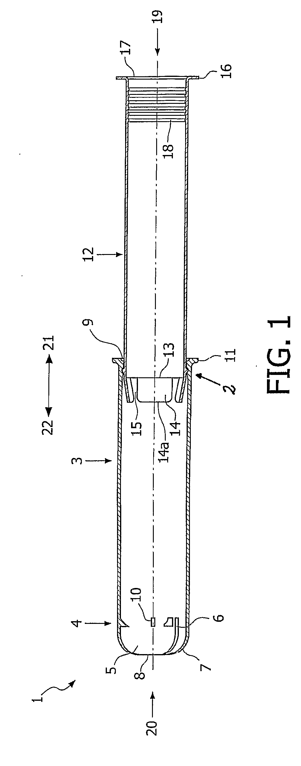
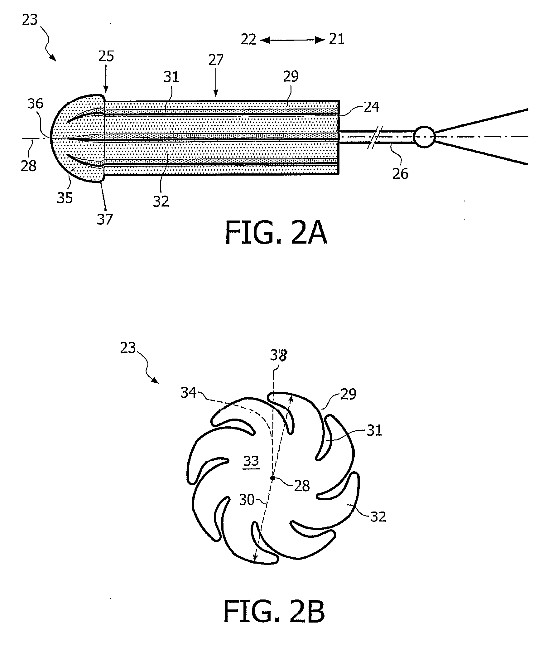
[0017]The invention is further explained with reference to FIGS. 1 to 4, which illustrate preferred, but non-limiting embodiments of the present assembly and of its parts, i.e., a compact tampon applicator 1 and a tampon 23.

[0018]The present assembly defines a proximal end 19 and a distal end 20. As used herein, the term “proximal end”19 refers to those portions of the assembly and of its parts that are most remote from the body of a user when the tampon 23 is being emplaced within a body cavity, e.g., a vaginal cavity. The term “distal end”20 refers to those portions of the assembly and of its parts that are closest to the body of a user when the tampon is being emplaced. Accordingly, the terms “proximal” or “proximally”, and “distal” or “distally”, as used herein, specify that a given portion or structure of the assembly or of its parts is relatively closer to, respectively, the proximal end 19 or the distal end 20 of the assembly or of its parts. Similarly, the terms “proximal di...


PUM


Abstract

A tampon applicator assembly is described which has a compact tampon applicator and a tampon having a longitudinal body defining an insertion end, a withdrawal end, a central section extending there between, a longitudinal axis, and an outer surface. The outer surface of the tampon has at least one area of radial depression.

Description

FIELD OF THE INVENTION[0001]This invention relates to tampon applicator assemblies and is particularly directed toward such assemblies provided in a compact, unobtrusive, conveniently short form.BACKGROUND OF THE INVENTION[0002]Most commercially available assemblies for introducing catamenial tampons intravaginally comprise a tampon disposed inside a tampon applicator consisting of a pair of telescoping tubes.[0003]In assemblies comprising a non-compact tampon applicator, a tampon is disposed in an outer tube which is combined with an ejector tube adapted to slideably expel the tampon from the outer tube. The ejector tube is smaller in diameter than the outer tube and is telescopically positioned therein so that by moving the ejector tube into one end of the outer tube, the tampon may be ejected from the opposite end. The outer tube is, of necessity, longer than the tampon and, to insure complete ejection of the tampon from the outer tube, generally the ejector tube is likewise long...

Claims


Application Information

Patent Timeline
Patent Type & Authority Applications(United States)
IPC IPC(8): A61F13/20
CPCA61F13/2034A61F13/263A61F13/26
Inventor VAN INGELEM, WERNERDE POORTER, ANNICKSMET, STEVEN
Owner ONTEX HIGIENEARTIKEL DEUT GMBH
Why Eureka
Try Eureka