Bone Augmentation Apparatus

Active Publication Date: 2008-08-14
IZI MEDICAL PROD
View PDF19 Cites 29 Cited by
  • Summary
  • Abstract
  • Description
  • Claims
  • Application Information

AI Technical Summary

Benefits of technology

[0005]It is therefore an object of the present invention to provide a novel bone augmentati

Problems solved by technology

However, also as described in Murphy #1, considerable care is required to reduce the likelihood of overfilling the vertebral body, as such overfilling can rupture the spinal cord and paralyze the patient.
Prior art syringes, connecting tubes and needles, however, can in some circumstances impede controlled and careful injection of bone cement into the vertebral body due to irregularities found along the channel between the syringe body and th

Method used


Image

  • Bone Augmentation Apparatus
  • Bone Augmentation Apparatus
  • Bone Augmentation Apparatus

Examples


Embodiment Construction

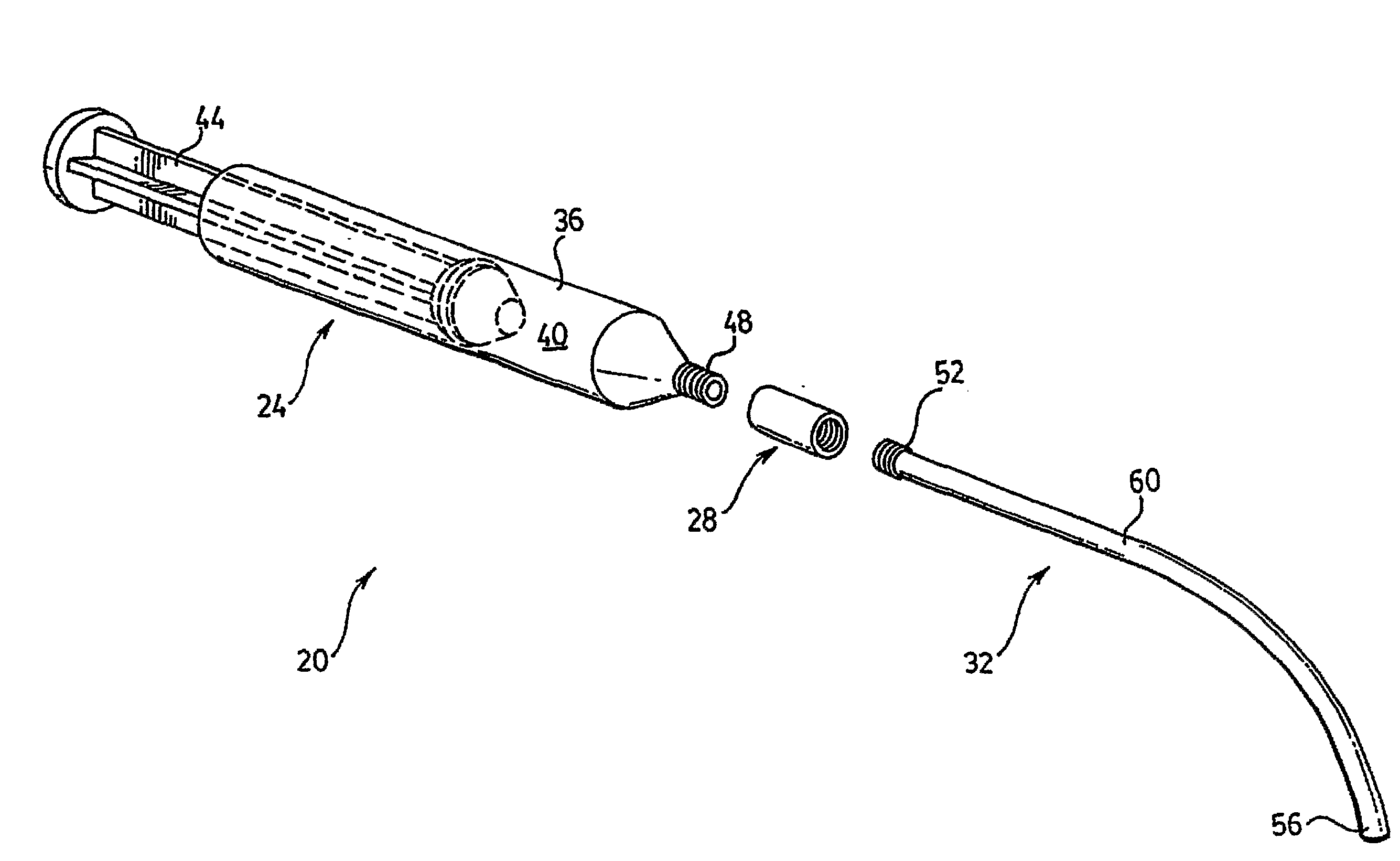
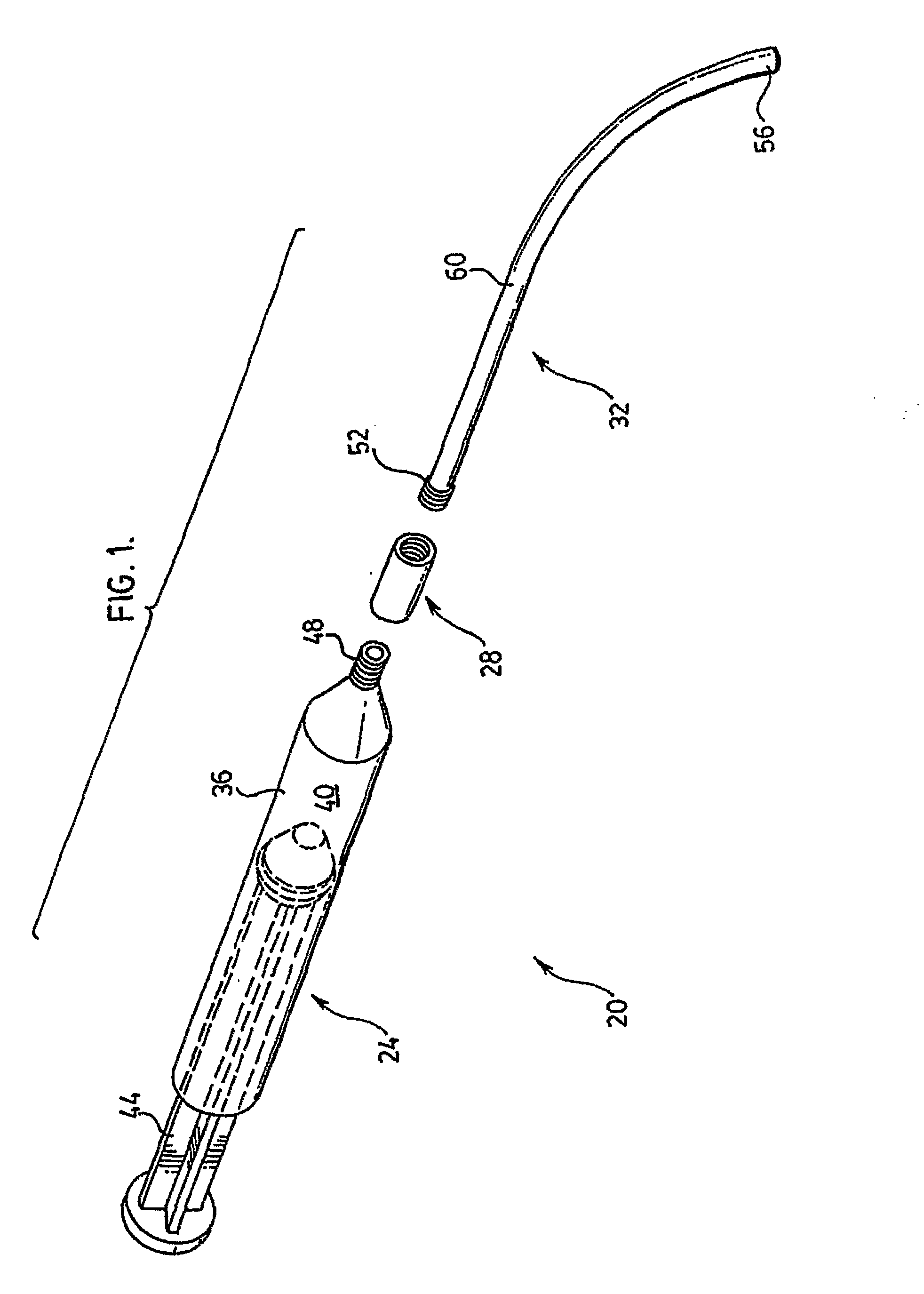
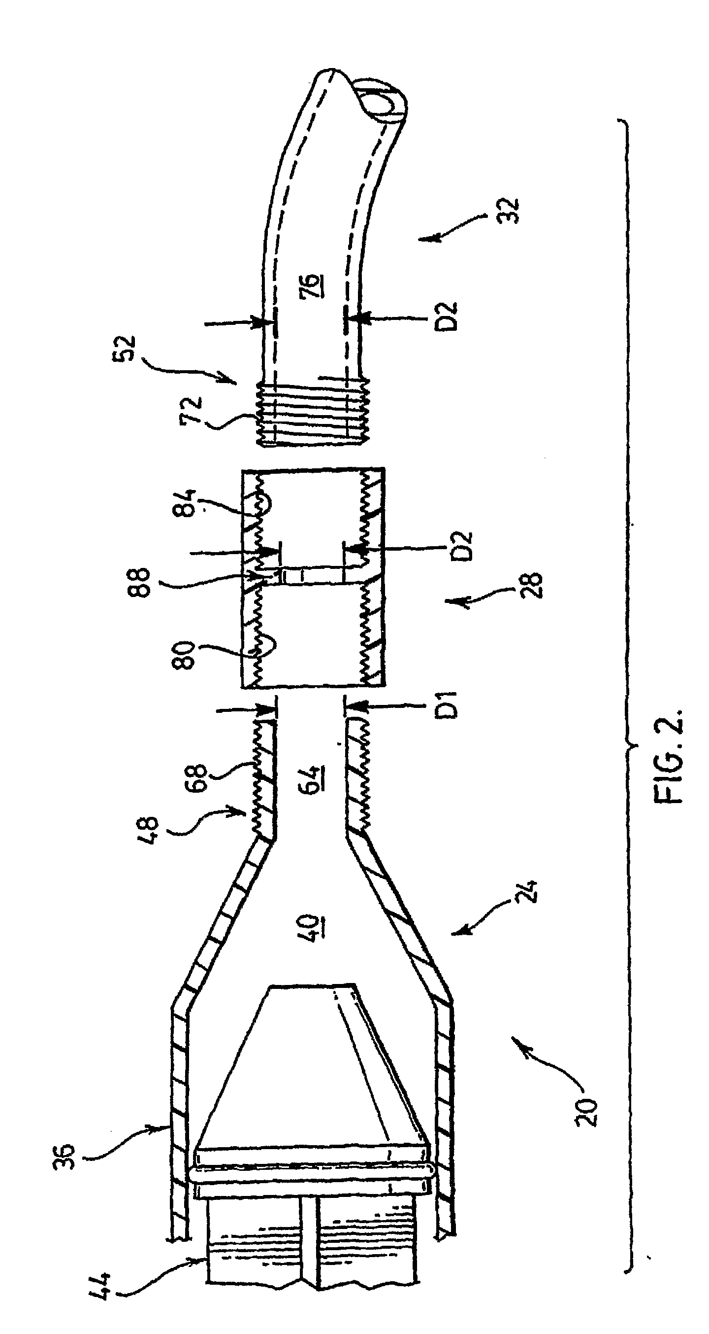
[0015]Referring now to FIG. 1, a bone cement delivery apparatus in accordance with an embodiment of the invention is indicated generally at 20. Apparatus 20 comprises a syringe 24, a connector 28 and a connecting tube 32. Apparatus 20 is used to deliver bone cement as part of a bone augmentation procedure, and in a present embodiment the procedure is vertebroplasty.

[0016]Syringe 24 comprises a barrel 36 defining a chamber 40 through which a plunger 44 can pass in order to express a bone cement (not shown) from a distal tip 48 of syringe 24.

[0017]Connector 28 provides a fitting which can be used to releasably couple syringe 24 to tube 32, such that a channel between tip 48 and tube 32 is substantially uniform with a channel defined by tube 32. Connector 28 will be discussed in greater detail below.

[0018]Tube 32 is made any suitable flexible material and has a length of from about 10 or about 15 centimeters (“cm”) to about 20 or about 30 cm; Tube 32 includes a proximal tip 52 that is ...


PUM


Abstract

A bone cement apparatus (20) is provided. In an embodiment, the apparatus includes a syringe (24) and a needle (120). The syringe and needle are interconnected by a connecting tube (32). Various fittings are employed to join the syringe, needle and connecting tube. The connecting tube and fittings present a pathway along which bone cement is carried. The connecting tube, fittings, and needle are all configured such that a substantially uniform pathway is provided from the end of the syringe to the end of the needle.

Description

FIELD OF THE INVENTION[0001]The present invention relates generally to bone augmentation and in particular an apparatus for performing bone augmentation.BACKGROUND OF THE INVENTION[0002]Vertebroplasty is a well-known procedure for augmenting a vertebrae that has collapsed due to osteoporosis or other indication. See, for example, U.S. Pat. No. 6,273,916 to Murphy (“Murphy #1”) and issued Aug. 14, 2001, the contents of which are incorporated herein by reference. In general terms, vertebroplasty involves transpedicular or posterolateral injection of a bone cement into the vertebral body.[0003]As is described in Murphy #1 and elsewhere, various types of bone cements can be used. One common bone cement is polymethylmethacrylate, but other types will occur to those of skill in the art. A common feature of many bone cements, is that they have a viscosity such that substantial pressure can be required to effect expression of the bone cement from the syringe, through any connective tubing a...

Claims


Application Information

Patent Timeline
IPC IPC(8): A61B17/58
CPCA61B17/3472A61B17/8811A61B17/8816A61F2002/4677A61F2/44A61F2/4611A61F2002/4623A61B17/8822A61F2/4603
Inventor MURPHY, KIERAN P.
Owner IZI MEDICAL PROD
Why Eureka
Try Eureka