Fire sprinkler head paint cover

Inactive Publication Date: 2008-08-21
COVERGUARDIAN
View PDF10 Cites 15 Cited by
  • Summary
  • Abstract
  • Description
  • Claims
  • Application Information

AI Technical Summary

Benefits of technology

[0005]The present invention comprises a fire sprinkler head paint cover which overcomes the foregoing and other shortcomings long since associated with the prior art. In accordance with the broader aspects of the invention a fire sprinkler head paint cover comprises a dome which receives the operating instrumentalities of the fire sprinkler head and a planar ring extending radially outwardly from the dome for engagement with the trim ring of the fire sprinkle

Problems solved by technology

The painting of surfaces having fire sprinkler heads therein involve inherent danger that the fire sprinkler heads will be damaged thereby releasing pressurized water.
Particularly in the case of

Method used


Image

  • Fire sprinkler head paint cover
  • Fire sprinkler head paint cover
  • Fire sprinkler head paint cover

Examples


Embodiment Construction

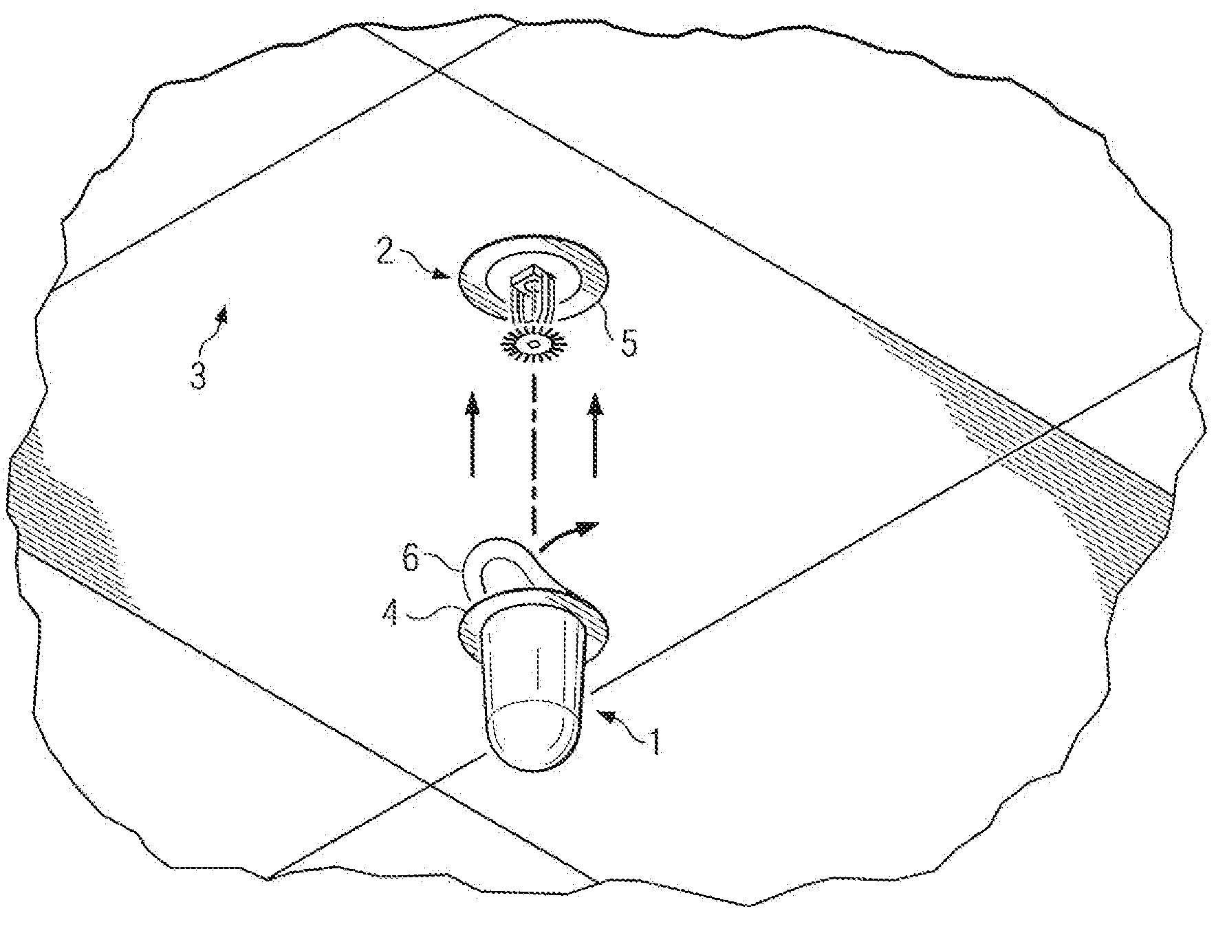
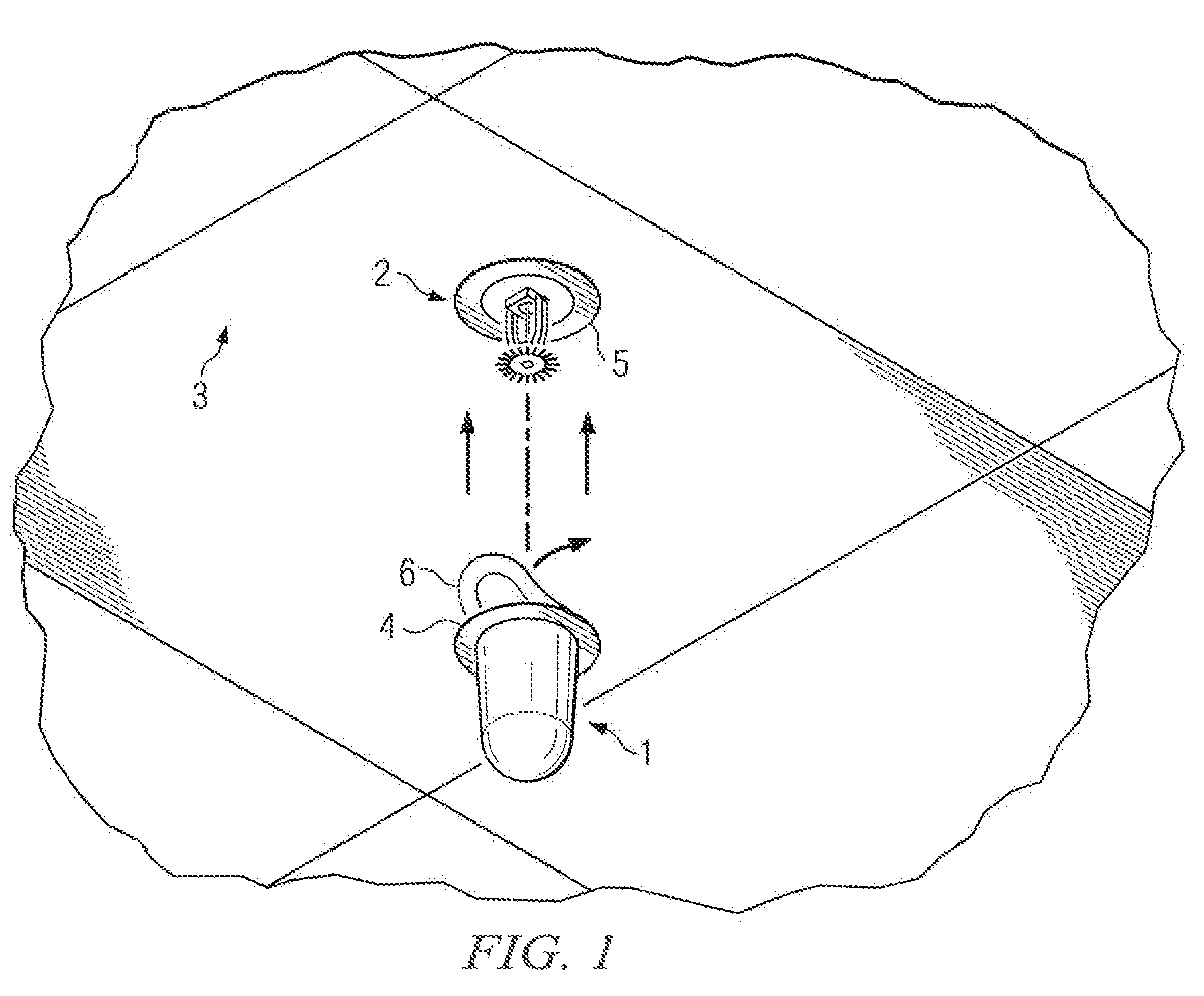
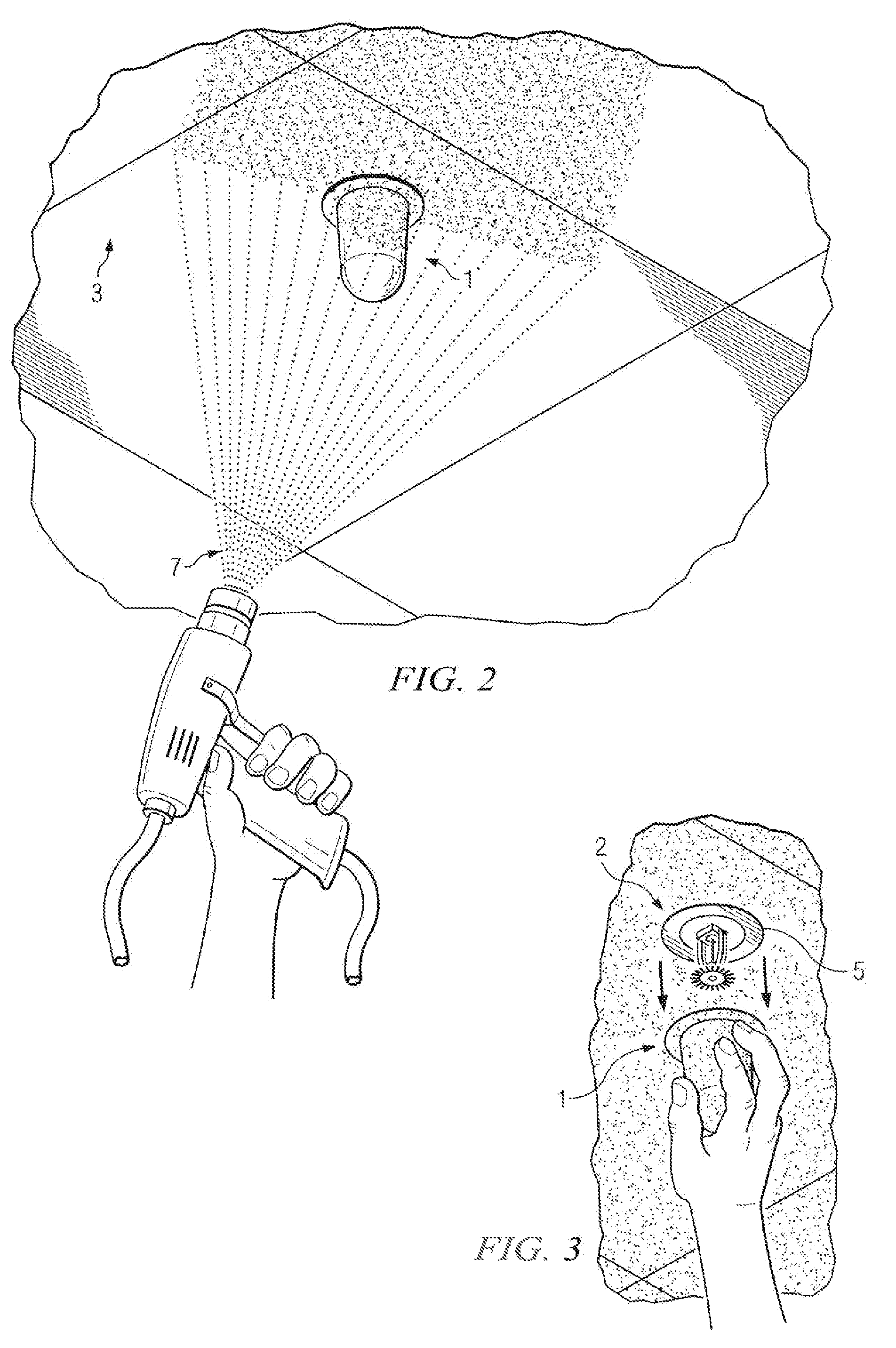
[0013]Referring to the drawings, and particularly to FIG. 1 thereof, a fire sprinkler head paint cover 1 comprising the present invention is illustrated. The fire sprinkler head paint cover 1 is configured so as to allow its application or placement over a fire sprinkler head 2 of an automatic fire sprinkler system. Here, the fire sprinkler head 2 is installed in a surface comprising a ceiling 3 it being understood that fire sprinkler heads are also installed in walls and other surfaces.

[0014]In the embodiment shown, the fire sprinkler head paint cover 1 is cylindrical or conical in shape, however, it is envisioned that the fire sprinkler head paint cover 1 can be of any shape and / or size conceivable, thereby enabling it to be placed over variously shaped fire sprinkler heads and / or fire sprinkler heads with different configurations. The fire sprinkler head paint cover 1 can be constructed of plastic or any other suitable material as desired, so long as the material is of proper wei...


PUM


Abstract

An easily removable fire sprinkler head paint cover to be temporarily installed over and around a fire sprinkler head so as to prevent paint or other finishing materials from coming into contact with a fire sprinkler head and to allow for uniform and systematic painting or finishing of walls or ceilings in which fire sprinkler heads are installed.

Description

TECHNICAL FIELD[0001]This invention relates to the painting of surfaces having fire sprinkler heads installed therein, and more particularly, to the protection of fire sprinkler heads during painting operations.BACKGROUND AND SUMMARY OF THE INVENTION[0002]As is well known, city, state, and federal regulations mandate the use of automated fire sprinkler systems in public and private buildings. Modern automated fire sprinkler systems comprise fire sprinkler heads which are typically of two types. The first type comprises a fusible solder link that prevents a plug from releasing and dispersing pressurized water. The fusible solder link melts at a predetermined temperature which allows the plug to release the pressurized water and put out a fire. The second and most common type of fire sprinkler head comprises a glass vial that prevents a plug from releasing and dispersing pressurized water. The glass vial contains a chemical that expands at a predetermined temperature thereby breaking ...

Claims


Application Information

Patent Timeline
IPC IPC(8): B65D41/02
CPCB05B15/045B05B12/20
Inventor MCKAY, DONALD ROBERTFLETCHER, DARRELL EDWARD
Owner COVERGUARDIAN
Why Eureka
Try Eureka