Valve flow adjustment device

Inactive Publication Date: 2008-08-21
FISHER CONTROLS INT LLC
View PDF5 Cites 3 Cited by
  • Summary
  • Abstract
  • Description
  • Claims
  • Application Information

AI Technical Summary

Benefits of technology

[0015]The device minimizes the drawbacks of the prior art while permitting a user to quickly change the maximum flow capacity of a valve or to decouple the flow adjustment device entirely via action taken outside of, or external to, the valve housing. Indeed, the operator may be able to make a flow adjustmen

Problems solved by technology

However, replacement of a valve plug and/or valve seat can necessitate disassembly and reassembly of the valve, which results in additional labor, and additional time the control valve is out of service.
However, the known devices tend to be fairly expensive and difficult to remove and install.
This may be due to the tendency to require serrations or threads along the valve stem, as well as along the internal surface of the travel limiting device which engages the valve stem.
Also, the devices tend to require removable bolts to fasten piec

Method used


Image

  • Valve flow adjustment device
  • Valve flow adjustment device
  • Valve flow adjustment device

Examples


Example

[0029]It should be understood that the drawings are not necessarily to scale.

[0030]While other plan and section views are not included, the details such views would show are considered to be adequately shown in the present views or well within the comprehension of those skilled in the art in light of the present disclosure. It also should be understood that the present invention is not limited to the examples illustrated.

DETAILED DESCRIPTION

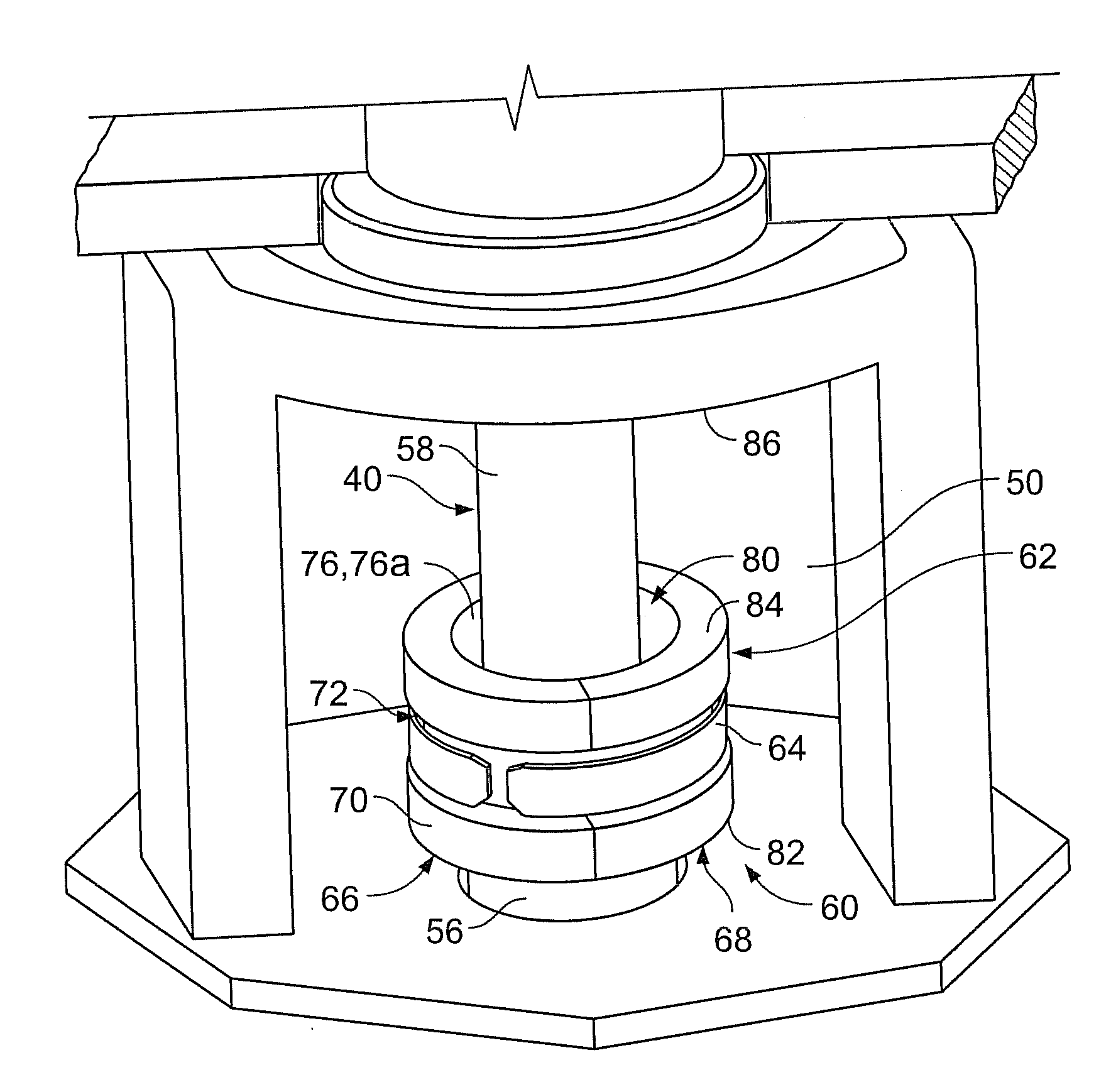
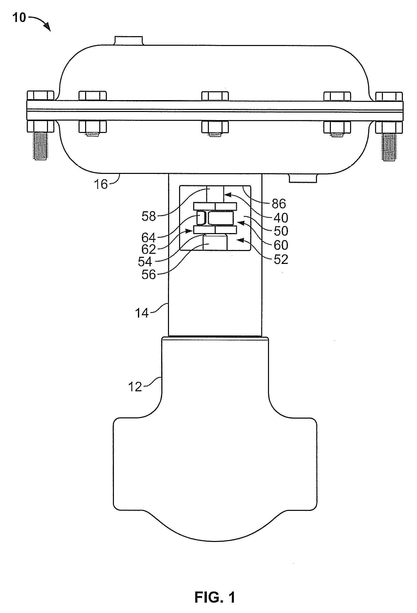
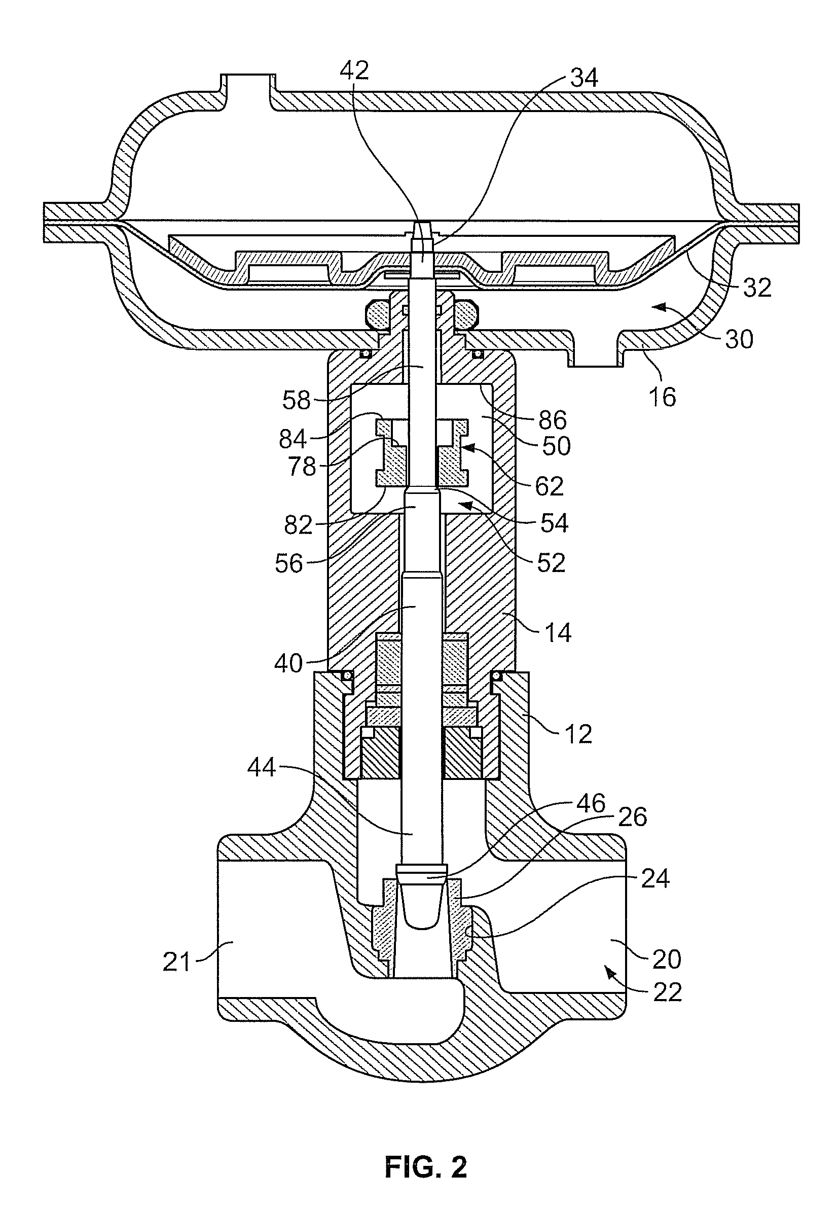
[0031]Referring now to the drawings, FIGS. 1 and 2 show an example of a control valve assembly 10 that includes a valve body 12 connected to a bonnet 14. The bonnet 14, in turn, is connected to a diaphragm casing 16. The diaphragm casing 16 houses a sliding stem actuator, which may take other forms. The sliding stem actuator can be of any suitable type for use with control valves. The control valve assembly 10 may be joined by conventional methods, such as flange mounting, to fluid piping components within a larger process control system.

[0032]Pa...


PUM


Abstract

A valve with a flow adjustment device in the form of a valve stem travel limiter includes a removable and reversible collar having a passage therethrough to receive a valve stem having a shoulder, the passage further includes two bores having different diameters. The flow adjustment device may be assembled to a valve stem to permit two different predetermined valve stem travel limits.

Description

FIELD OF THE DISCLOSURE[0001]The disclosure relates generally to control valves having a valve stem movable for flow rate adjustment and, more particularly, to travel limiters for such valve stems to adjust maximum available flow rate.BACKGROUND[0002]Typically, a control valve includes a fluid inlet passage coupled through an orifice to a fluid outlet passage and a closure member disposed in the orifice, which controls the amount of fluid flow therethrough. The closure member may include a valve plug having a surface which engages the orifice forming a valve seat. During operation of a process control system, a process controller may issue a command signal to a control valve to move the valve plug toward or away from engagement with the valve seat to provide a desired fluid flow through the orifice and, therefore, the control valve.[0003]Control valves typically experience variable process conditions during their lifetime. A gas well, for example, may have high pressure when first d...

Claims


Application Information

Patent Timeline
IPC IPC(8): F16K51/00F16K31/12
CPCF16K31/126
Inventor GETHMANN, DOUGLAS PAUL
Owner FISHER CONTROLS INT LLC
Why Eureka
Try Eureka