Cabinet assembly having a releasable support foot

a cabinet and support foot technology, applied in the direction of furniture joining parts, fastening means, domestic applications, etc., can solve the problems of unappealing, unfavorable use, unnecessary space occupied by the support assembly, etc., to reduce time and effort, improve functionality and usability

Active Publication Date: 2018-04-10
NEWAGE PROD
View PDF29 Cites 0 Cited by
  • Summary
  • Abstract
  • Description
  • Claims
  • Application Information

AI Technical Summary

Benefits of technology

[0011]In this way, the assembly of the present invention provides improved functionality and usability in securing a support foot to a cabinet assembly and, at the same time, reduces the time and effort required to secure the support foot to the cabinet assembly.

Problems solved by technology

The support assembly takes up unnecessary space, adds weight to whatever surface or shelf the cabinet assembly is supported by, and is aesthetically unappealing.
Despite the convenience afforded by common cabinet assemblies to include support assemblies capable of detaching from the cabinet assembly, the process of releasing support assemblies is generally time consuming and requires tools that may not be readily available.

Method used


Image

  • Cabinet assembly having a releasable support foot
  • Cabinet assembly having a releasable support foot
  • Cabinet assembly having a releasable support foot

Examples


Embodiment Construction

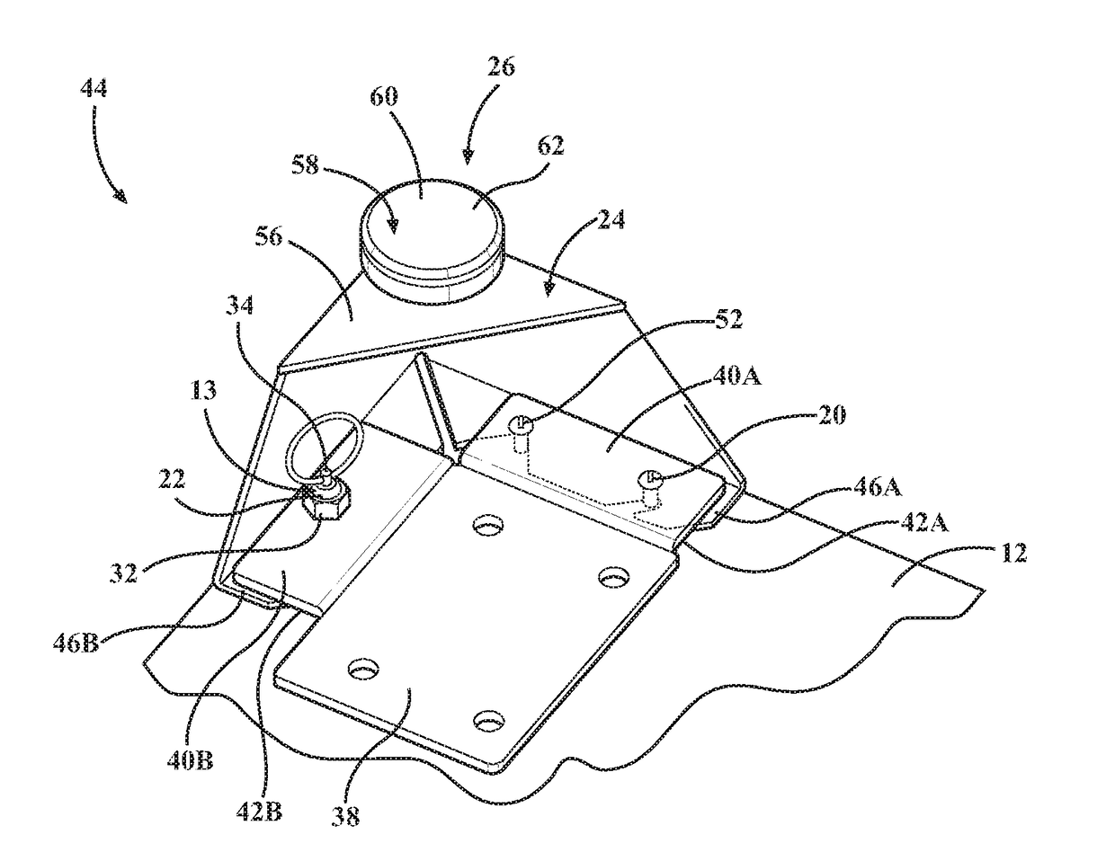
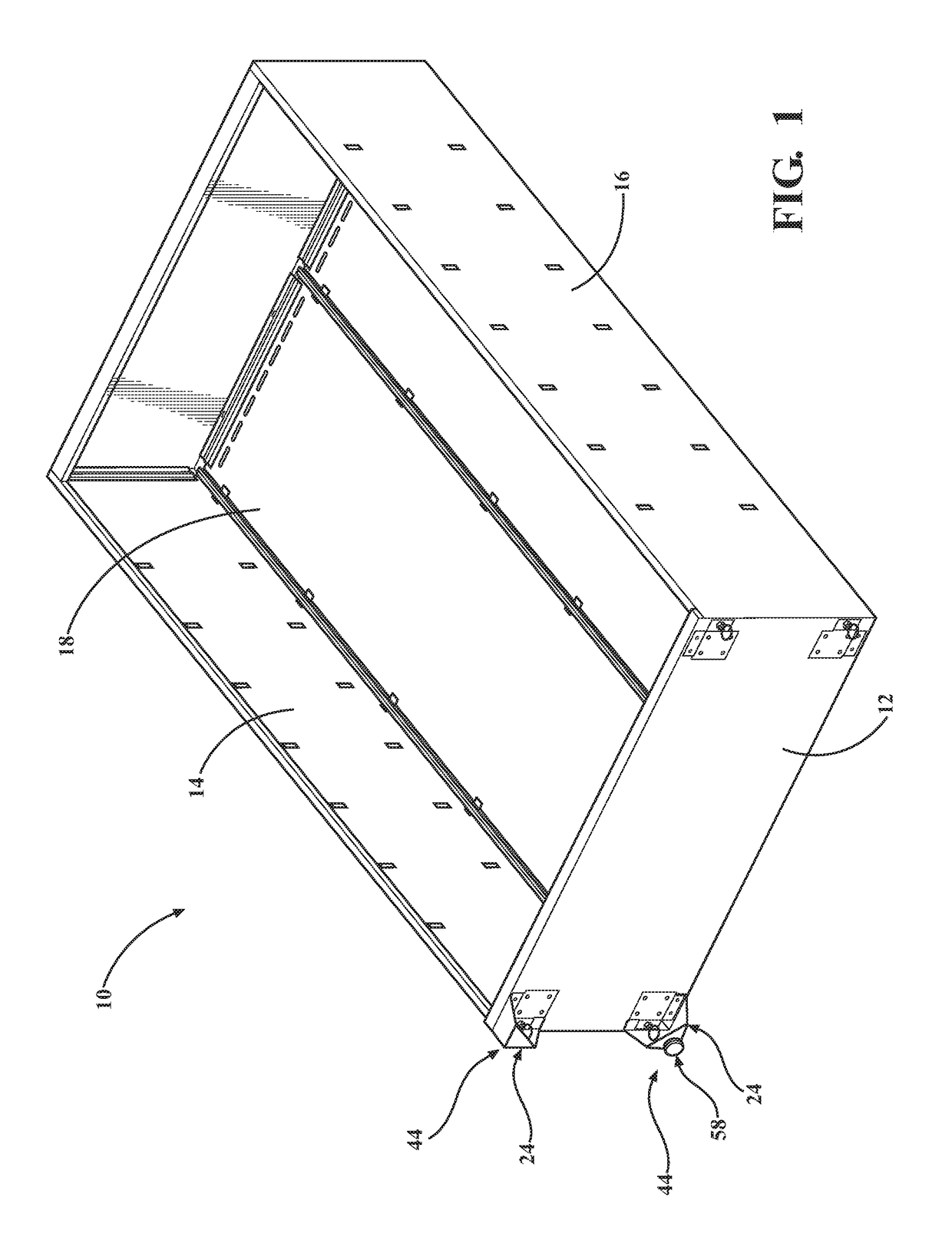
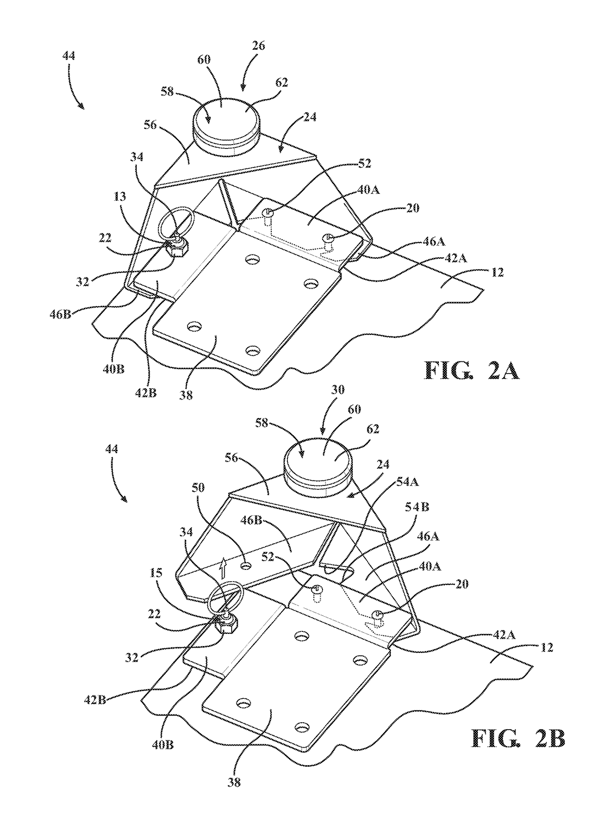
[0023]Referring now to the figures, wherein like numerals indicate corresponding parts throughout the several views, a cabinet assembly 10 is generally shown in FIG. 1. Generally, the cabinet assembly 10 includes a base 12 and walls 14,16 secured to the base 12 to define an interior 18. The cabinet assembly 10 may further include a top and a back panel. The cabinet assembly 10 may additionally include shelves or drawers disposed within the interior 18 and coupled to one of the base 12, walls 14,16, top, and back panel. As such, the cabinet assembly 10 may be an enclosed cabinet, such as shown, an open cabinet or book shelf without doors, a dresser, a credenza, a cupboard, a cabinet with any combination of drawers, doors, and shelves, a cabinet as a sub-component of a desk, or any other storage structure having a base 12 and walls 14,16. The base 12, walls 14,16, top, and back panel may be integrally formed with each other in any combination. Alternatively, the base 12, walls 14,16, ...


PUM


Abstract

A cabinet assembly includes a base and walls secured to the base to define an interior. The cabinet assembly further includes a pivot pin coupled to the base and a locking device coupled to the base. The locking device is movable relative to the base between an engaged position and a released position. The cabinet assembly additionally includes a support foot. The support foot is fixed to the base in a first orientation when the locking device is in the engaged position. The support foot is movable about the pivot pin to a second orientation spaced from the locking device when the locking device is in the released position.

Description

BACKGROUND OF THE INVENTION[0001]1. Field of the Invention[0002]The present invention relates, generally, to a support assembly for a cabinet assembly.[0003]2. Description of the Related Art[0004]Cabinet assemblies known in the art generally include a top, a base, and side walls coupled to the top and base. Cabinet assemblies may be hung on a wall, rest on a shelf, rest on a floor surface, or be otherwise supported. When the cabinet assembly is supported on a floor surface, the cabinet assembly generally includes a support assembly coupled to the base to space the base from the floor surface.[0005]Typically, configurations of cabinet assemblies hanging on a wall or resting on a shelf do not include a support assembly attached to the base. There are many reasons for this. The support assembly takes up unnecessary space, adds weight to whatever surface or shelf the cabinet assembly is supported by, and is aesthetically unappealing.[0006]In some instances, it may be necessary to move a...

Claims


Application Information

Patent Timeline
Patent Type & Authority Patents(United States)
IPC IPC(8): A47B91/00A47B96/06A47B91/16A47B91/02
CPCA47B91/02A47B96/06A47B91/16A47B2220/0027A47B91/04A47B91/024F16B12/36F16B12/38A47B2230/07
Inventor VANDENHAM, ROBERT
Owner NEWAGE PROD
Why Eureka
Try Eureka