Specimen pre-treatment apparatus and specimen holder

a pre-treatment apparatus and specimen technology, applied in the direction of instruments, nuclear engineering, irradiation devices, etc., can solve the problems of limiting the shape of the specimen, limiting the position, and the glow discharge tube b>7/b> of the conventional specimen pre-treatment apparatus may be unfortunately provided insufficient sealing, so as to prevent the possibility of contamination of the observation surface and reduce time and effort

Inactive Publication Date: 2009-10-01
HORIBA LTD
View PDF0 Cites 3 Cited by
  • Summary
  • Abstract
  • Description
  • Claims
  • Application Information

AI Technical Summary

Benefits of technology

[0015]The present invention further aims to provide a specimen pre-treatment apparatus and a specimen holder that are capable of reducing time and efforts for the observation of the specimen with an SEM, and preventing the contamination possibility of the observation surface.
[0039]According to the twelfth aspect, the specimen support end of the specimen support part has a table-like hole that can detach the table-like member, such as e.g. the specimen support member for the exclusive use of the SEM, which places the specimen. In other words, the specimen holder holds the specimen by attaching the table-like member that places the specimen. This configuration reduces the time and efforts that are required to observe the specimen having the observation surface with the SEM or the like. Accordingly, it reduces the chance that the surface of the specimen is exposed to air and contaminated. Thus, the observation surface of the specimen can be kept under the satisfactory condition for observation.

Problems solved by technology

Thus, the specimen holder 8 cannot produce the glow discharge when the specimen S has a shape that incompletely closes the opening 81, such as an elongate specimen S. As described above, the conventional specimen pre-treatment apparatus may limit the shape of the specimen S, unfortunately.
Furthermore, the glow discharge tube 7 of the conventional specimen pre-treatment apparatus may be unfortunately provided insufficient sealing, when a plate-like specimen S is arranged vertically with respect to the opening 81, or when an edge of a specimen S is arranged at the position of the opening 81.
Thus, the conventional specimen pre-treatment apparatus may limit a position where the observation surface is formed on the specimen S, unfortunately.
A user may desire to adjust the speed for cleaning and smoothing or the shape of the observation surface according to the type or the use purpose of the specimen S. However, the conventional specimen pre-treatment apparatus unfortunately cannot adjust the position of the specimen S, because the position of the specimen S is pressed and fixed by the spring 83 in the specimen holder 8.
Thus, the conventional specimen pre-treatment apparatus cannot adjust the speed for cleaning and smoothing or the shape of the observation surface through the adjustment of the distance between the specimen S and the leading end of the electrode 72, unfortunately.
When the specimen S is exposed to air for a long time after forming the observation surface, the observation surface is contaminated by an oxide film or dust.
However, as described above, the conventional specimen pre-treatment apparatus takes time and efforts to observe the specimen S having the observation surface with the SEM.
Therefore, the observation surface of the specimen S might be contaminated.

Method used


Image

  • Specimen pre-treatment apparatus and specimen holder
  • Specimen pre-treatment apparatus and specimen holder
  • Specimen pre-treatment apparatus and specimen holder

Examples


Embodiment Construction

[0054]The present invention will be described below with reference to the drawings showing embodiments thereof.

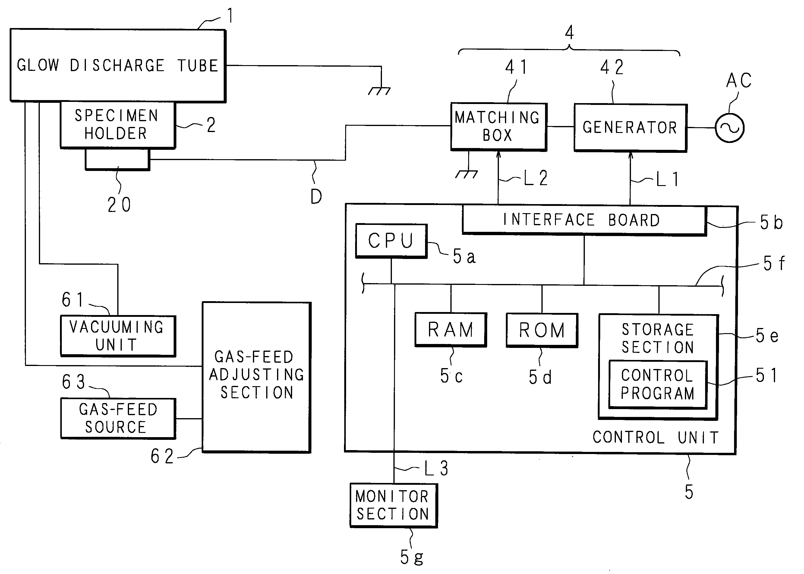
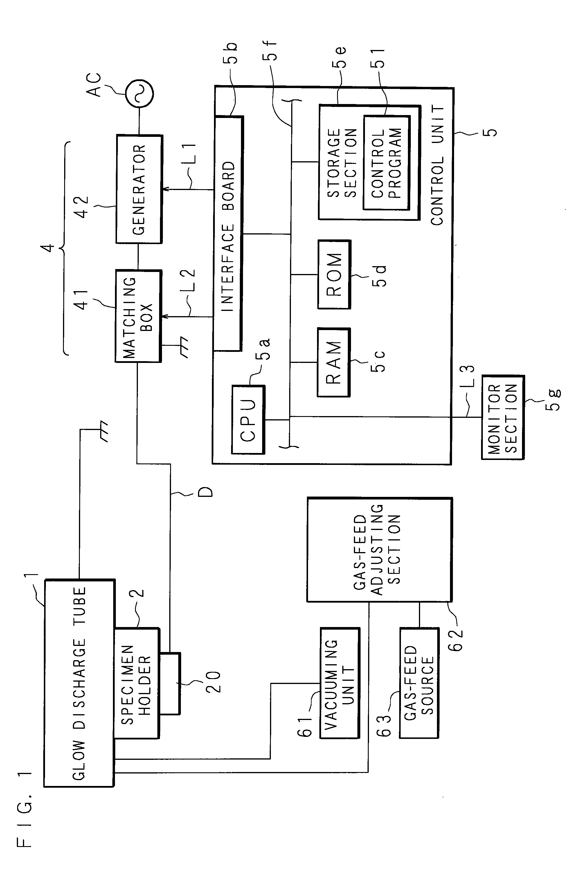
[0055]FIG. 1 is a block diagram showing the structure of a specimen pre-treatment apparatus according to the present invention. The specimen pre-treatment apparatus comprises a glow discharge tube 1 for generating a glow discharge, a specimen holder 2 that holds a specimen which is subjected to a pre-treatment, such as etching, cleaning, sputtering, milling or the like, a power source section 4 that produces power for an applied voltage to generate the glow discharge, and a control unit 5 that totally controls the specimen pre-treatment apparatus. The power source section 4 has a generator 42 and a matching box 41 that are connected to an AC power source AC (220 V in the present embodiment) for generating high-frequency power. The generator 42 and the matching box 41 are respectively connected to the control unit 5. The glow discharge tube 1 and the matching box 41 are set ...


PUM


Abstract

In a specimen pre-treatment apparatus, a specimen support part is screwed in a hollow column casing part while facing a specimen support end toward the same direction as an open end of the hollow column casing part. A specimen holder is arranged so that the specimen support end which supports a specimen is opposite to an end portion of an anode (electrode). The change of the screwing depth can adjust a position of the specimen support part with respect to the hollow column casing part. Accordingly, it allows adjusting the distance between the specimen that is supported by the specimen support part and the end portion of the anode.

Description

[0001]This Nonprovisional application claims priority under 35 U.S.C.§119(a) on Patent Application No. 2008-84222 filed in Japan on Mar. 27, 2008, the entire contents of which are hereby incorporated by reference.BACKGROUND OF THE INVENTION[0002]1. Field of the Invention[0003]A certain aspect of the embodiment discussed herein is related to a specimen pre-treatment apparatus and a specimen holder for forming a specimen into a shape suitable for a measurement by a glow discharge in order to form a thin specimen that is to be measured by e.g. a transmission electron microscope.[0004]2. Description of Related Art[0005]Conventionally, a scanning electron microscope (SEM) may be used in order to visually observe a structure or tissue of a specimen. The observation surface of the specimen may have to be pre-treated, in a preparation process, in order to be observed by means of the SEM. This pre-treatment process may expose, clean and smoothe the observation surface at the desired position...

Claims


Application Information

Patent Timeline
Patent Type & Authority Applications(United States)
IPC IPC(8): G21K5/10
CPCG01N1/286G01N1/28
Inventor HIRANO, AKIHIROIWASAKI, SHUNSUKE
Owner HORIBA LTD
Why Eureka
Try Eureka