Transmission Of Power Supply For Robot Applications Between A First Member And A Second Member Arranged Rotatable Relative To One Another

a technology for robot applications and power supply, which is applied in the direction of transformer/inductance circuits, circuit arrangements, inductances, etc., can solve the problems of difficult repair, difficult detection of contact failure or media leakage, and wear of individual cable parts and hoses of cabling

Inactive Publication Date: 2008-08-21
ABB RES LTD
View PDF6 Cites 239 Cited by
  • Summary
  • Abstract
  • Description
  • Claims
  • Application Information

AI Technical Summary

Benefits of technology

[0030]According to an embodiment of the second aspect of the invention the supplying of a second high frequency ac current to a first coil in the first part further compri...

Problems solved by technology

Due to the complex twisting and bending of the cabling the individual cable parts and hoses of the cabling are often worn out or begins to operate in failure.
The appearances of a contact failure or media leakage is difficult to detect and also difficult to repair.
Besides, the cabling arrangement on the outside of the robot trespasses the working space and sometimes blocking the performance of the robot.
Still the cabling is worn and sometimes torn by this twisting and bending movements.
The presence of contact failure in only one part of the process cabling may necessitate the whole cabling to be replaced.
The replacement of the cabling, especially inside the robot arms, may put the robot out of production for a considerable period of time.
This affects the production time.
Any disturbance in the contact between the pin and the slip ring will cause a transient in the electric signal.
The frequent sliding of the pin against the slip ring will wear the slip ring and finally cause a contact failure between the pin and the slip ring.
There will always be infinitesimal moments of non contact, which will disturb the electric communication over the swivel connection.
Each additional shoe causes however due to friction a raise in the torque needed for rotation.
The increased force leads to higher fri...

Method used


Image

  • Transmission Of Power Supply For Robot Applications Between A First Member And A Second Member Arranged Rotatable Relative To One Another
  • Transmission Of Power Supply For Robot Applications Between A First Member And A Second Member Arranged Rotatable Relative To One Another
  • Transmission Of Power Supply For Robot Applications Between A First Member And A Second Member Arranged Rotatable Relative To One Another

Examples


second embodiment

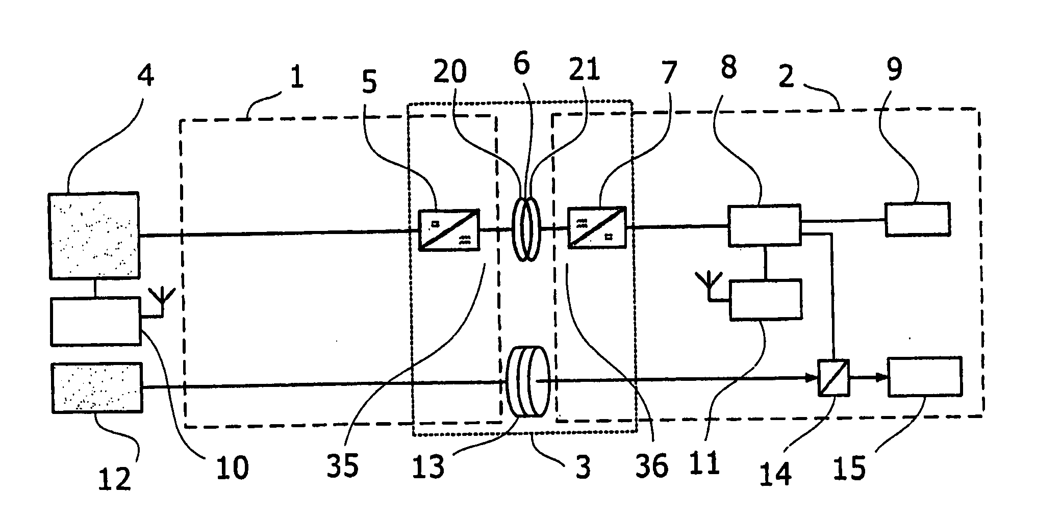
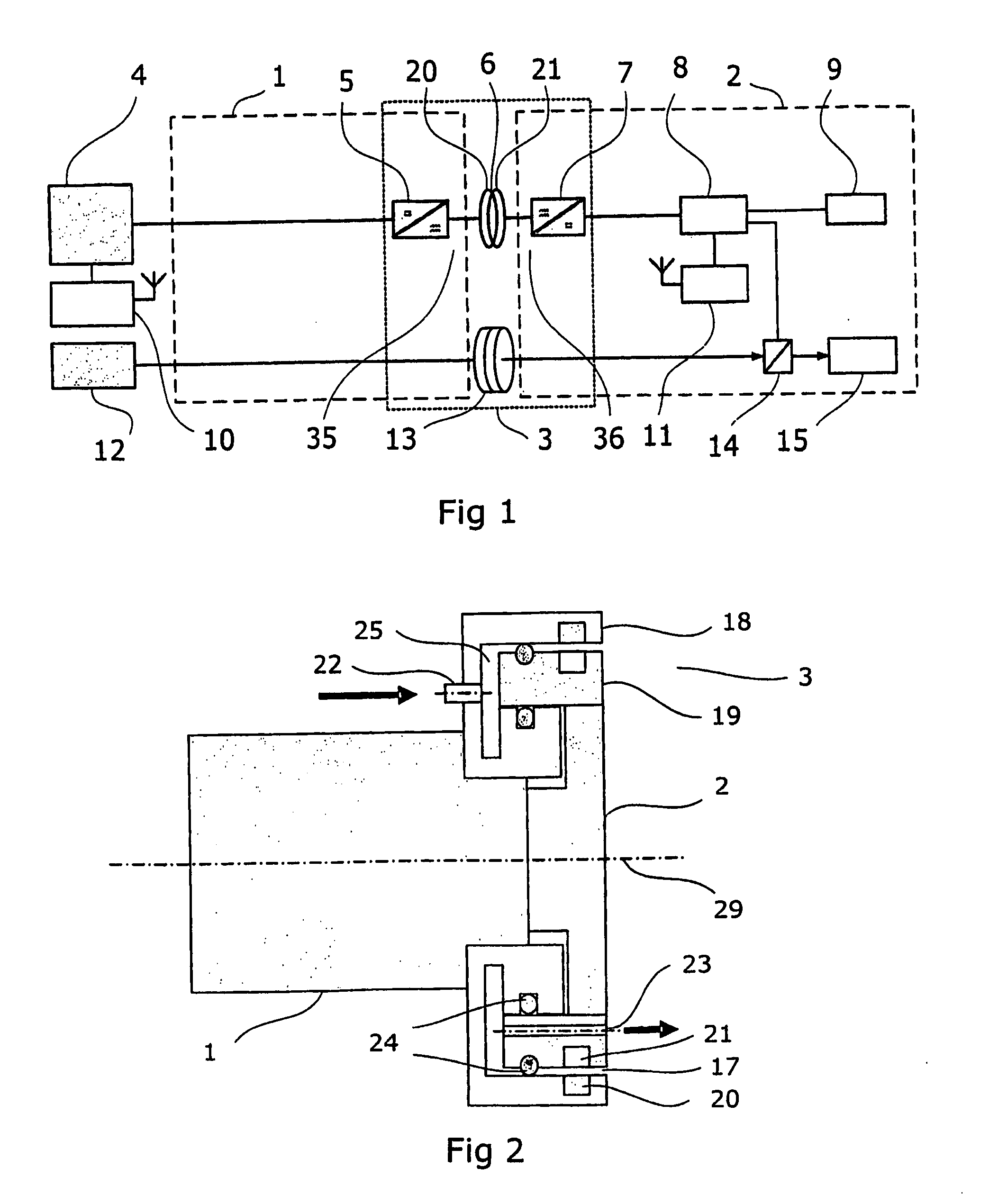
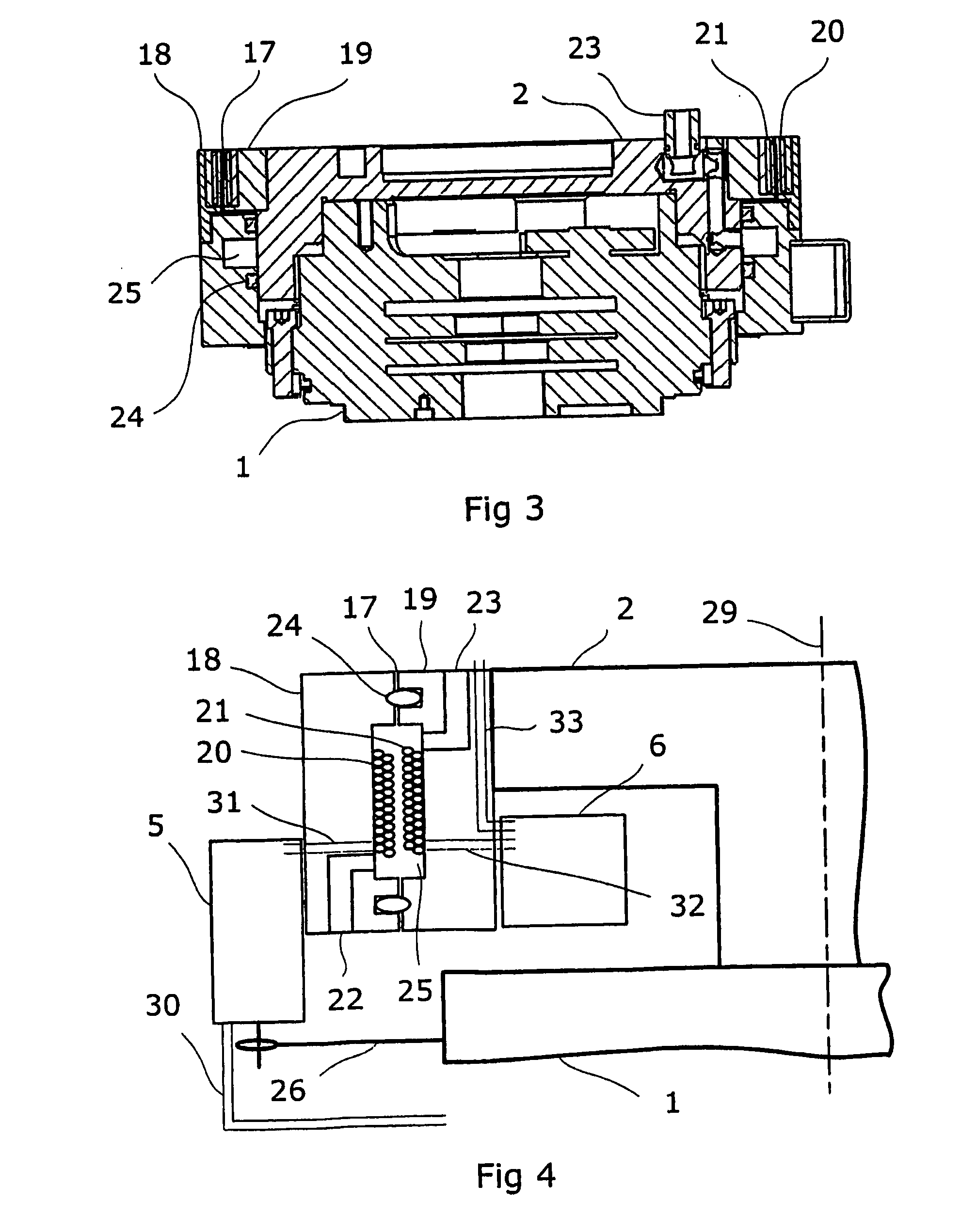
[0049]the process media supply unit is shown in FIG. 3. A first part 18 comprising a first coil 20 in an open cavity is attached to the first robot part 1. A second part 19 comprising a second coil 21 in an open cavity is attached to the second robot part 2. The first and second part is separated by an airgap 17. The first and second coil is arranged to form a rotating electric power transfer unit for magnetic flux interaction across the airgap. In this embodiment the cavity 25 is formed as a circular groove in the first part 18. The groove is sealed off by a resilient tightening band 24 on each side of the groove. The cross section of the resilient tightening band has a square shape. Both of the resilient tightening bands are positioned on the same side of the second part. In order to protect the coils from receiving particles or dust from the environment the first or second part may comprise a lip to cover the airgap.

third embodiment

[0050]the process media supply unit is shown in FIG. 4. A first part 18 comprising a first coil 20 of a rotating electric power transfer unit is attached to the first robot part 1. A second part 19 comprising a second coil 21 of the rotating electric power transfer unit is attached to the second robot part 2. In this embodiment the cavity 25 is formed as circular grooves in both the first part 18 and the second part 19. The grooves are sealed off by resilient tightening bands 24 on each side of the cavity. In the example the cross section of the tightening bands has an oval shape. A first media channel 22 in the first part 18 is in fluid communication with the cavity 25. A second media channel 23 in the second part 19 is also in fluid communication with the cavity 25. Thus the fluid media supply passes through the first channel, the cavity and the second channel.

[0051]In the embodiment shown in FIG. 4 the cavity 25 contains both the first coil 20 and the second coil 21 of the rotati...


PUM


Abstract

A process media transfer unit for an industrial robot including a first part for attachment to a first robot part, and a second part for attachment to a second robot part. The first and second parts being coaxially arranged about a common axis and separated by an airgap to provide an endless rotation relative to each other.

Description

TECHNICAL FIELD[0001]The present invention concerns the transfer of process media in an industrial robot.BACKGROUND OF THE INVENTION[0002]In an industrial robot there is a need for transfer of process media within the robot and to a tool carried by the robot. Process media most commonly comprises compressed air, cooling fluids, electric power electric signals and such. It is known to assemble all these process media in a process cabling. Thus, a process cabling comprises a plurality of electric wires and hoses. The wires and hoses may be bundled together and protected by a flexible tube. In a known arrangement the cabling is arranged on the outside of the articulated robot parts and arms for process media supply to the tool. Since the robot is capable of moving the tool in very complex patterns the cabling must be very flexible to be capable of following these movements. Due to the complex twisting and bending of the cabling the individual cable parts and hoses of the cabling are of...

Claims


Application Information

Patent Timeline
IPC IPC(8): H01F38/00B25JB25J19/00H01F38/14H02J5/00
CPCB25J19/0029H02J5/005H01F38/14H02J50/80H02J50/10
Inventor KREITZ, ANDREASWALDI, WOLFGANGHUG, KUNOGENTZELL, TOBIASKJELLSSON, JIMMYFREY, JAN-ERIK
Owner ABB RES LTD
Why Eureka
Try Eureka