Impedance controlled electronic lamp circuit

a technology of electronic lamp circuit and impedance control, which is applied in the direction of electric variable regulation, process and machine control, instruments, etc., can solve the problems of increasing negative resistance, increasing ballast output voltage, and inability of ballast to properly drive such a load

Inactive Publication Date: 2008-08-21
MARLEX ENG
View PDF8 Cites 75 Cited by
  • Summary
  • Abstract
  • Description
  • Claims
  • Application Information

AI Technical Summary

Benefits of technology

[0006]In view of the foregoing disadvantages inherent in known electronic lamps, the present invention provides a novel lamp ballast impedance controlled electronic lamp circuit wherein the circuit can be utilized for allowing a variety of electronic light emitting devices to be powered by a lamp ballast.

Problems solved by technology

A problem with conventional electronic lamps is that they often use an electronic circuit to regulate a constant current supplied to the light emitting devices (LEDs).
This produces an incremental negative resistance as a load to the ballast they are connected to, however, a typical ballast cannot properly drive such a load.
This condition causes a ballast to operate at some output level below its intended operating point or can cause a runaway condition that causes the ballast output voltage to increase to the point that can destroy the LED lamp components.
Another problem with conventional electronic lamps is that they often use a transformer to match the ballast output voltage to the LED string voltage.
However, the LED forward voltage changes due to operating temperature and aging effects.
This change causes the optimized operating point to shift to a less efficient one because the effective load impedance the ballast sees changes.
Another problem with conventional electronic lamps is that they often only connect to one electrode at both ends of the tube leaving one electrode at both ends of the tube unconnected.
This can cause three problems when used with some ballasts.
Such capacitors are typically in series with one of the two electrodes at either end of the tube in ballasts using voltage mode filament heating which results in a change in the load seen by the ballast and thus a shift in the operating point away from the optimum value.
Second, in the case of rapid start ballasts that utilize current mode filament heating, the LED lamp is connected to an electrode which, in turn, is connected to a free floating capacitor inside the ballast, thereby providing no continuous electrical path in the lamp circuit and preventing the LED lamp from turning on.

Method used


Image

  • Impedance controlled electronic lamp circuit
  • Impedance controlled electronic lamp circuit
  • Impedance controlled electronic lamp circuit

Examples


Embodiment Construction

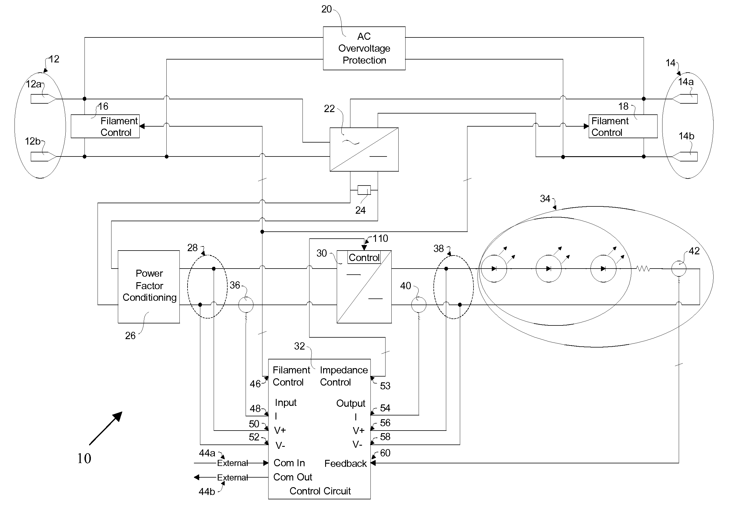
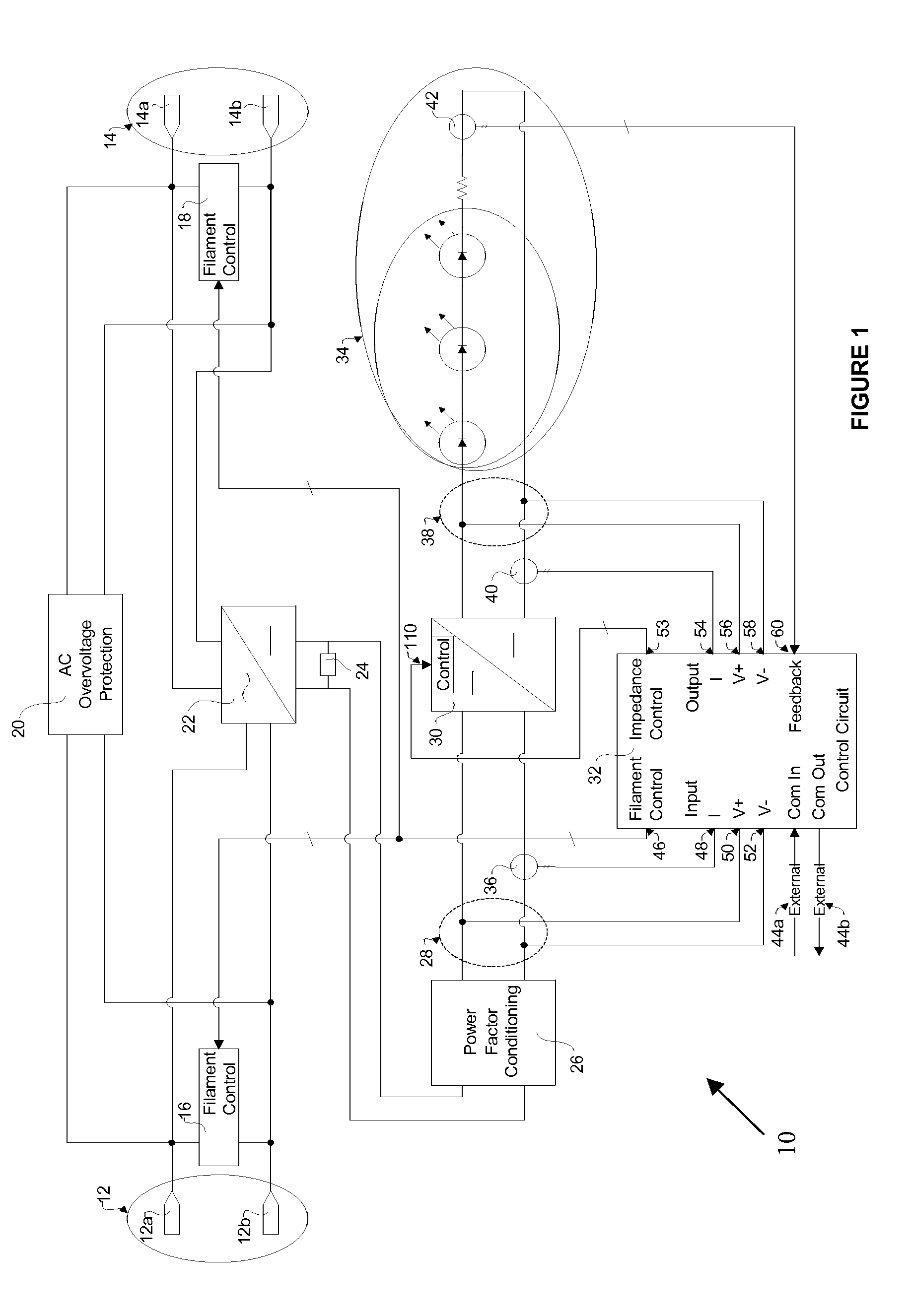
[0027]Turning to FIG. 1, a schematic diagram of an impedance controlled electronic lamp circuit is shown. In the preferred embodiment, the circuit 10 comprises a first, power source, or ballast connector 12 including a first, power source, or ballast connection 12a and a second, power source, or ballast connection 12b which form a two pin connector for connection to the ballast output of a first filament of the lamp and a second, power source, or ballast connector 14 including a first, power source, or ballast connection 14a and a second, power source, or ballast connection 14b which form a two pin connector for connection to the ballast output for a second filament of the lamp. The first ballast connector 12 and the second ballast connector 14 provide an apparatus or means to electrically connect the circuit 10 to form a connection between the circuit 10 to the lamp output. In one embodiment, this can be implemented via a suitable connector or a set of lead wires. In a preferred em...


PUM


Abstract

There is provided lamp ballast impedance controlled electronic lamp circuit, powered by a lamp ballast, for controlling a set of light emitting devices and being, comprising at least one connector, for connecting to the lamp ballast; and for receiving an AC signal; at least one filament control, associated with one of the at least one connector; a circuit for transforming the AC signal to a DC signal; a power convertor circuit; for receiving the DC signal and for processing the DC signal to provide a signal to power to the set of light emitting devices; a control and monitoring circuit; wherein the control and monitoring circuit monitors the DC signal and controls the impedance of either the at least one filament control or the power convertor circuit to control the set of light emitting devices.

Description

CROSS REFERENCE TO RELATED APPLICATION[0001]This application claims the benefit of priority of U.S. Provisional Patent Application No. 60 / 890,567 filed Feb. 19, 2007, which is incorporated herein by reference in its entirety.FIELD OF THE INVENTION[0002]The present invention relates generally to electronic lamps and more specifically to a lamp ballast impedance controlled electronic lamp circuit for allowing a variety of electronic light emitting devices to be powered by a lamp ballast.BACKGROUND OF THE INVENTION[0003]A problem with conventional electronic lamps is that they often use an electronic circuit to regulate a constant current supplied to the light emitting devices (LEDs). This produces an incremental negative resistance as a load to the ballast they are connected to, however, a typical ballast cannot properly drive such a load. This condition causes a ballast to operate at some output level below its intended operating point or can cause a runaway condition that causes the...

Claims


Application Information

Patent Timeline
Patent Type & Authority Applications(United States)
IPC IPC(8): H05B37/02
CPCH05B33/0815Y02B20/383H05B33/0827H05B33/0821H05B45/40H05B45/46H05B45/38H05B45/00H05B45/355Y02B20/30H05B45/3725
Inventor SCHAIBLE, UWE D.VON STYP-REKOWSKI, NORMAN H.
Owner MARLEX ENG
Why Eureka
Try Eureka