Method and apparatus to reduce pwm voltage distortion in electric drives

a technology of electric drives and voltage distortion, applied in the field of voltage source inverters, can solve the problems of imposing limitations on the minimum, affecting the operation of the gate drive circuit, and not being ideal for switching, so as to reduce the voltage distortion effect of electric drives

Active Publication Date: 2008-08-21
GM GLOBAL TECH OPERATIONS LLC
View PDF6 Cites 17 Cited by
  • Summary
  • Abstract
  • Description
  • Claims
  • Application Information

AI Technical Summary

Benefits of technology

[0007]Methods and apparatus are provided for controlling a voltage source inverter that reduces voltage distortion effects in electric drives. In an exemplary embodiment, a method for controlling a voltage source inverter is provided. The voltage source inverter has minimum and maximum pulse widths (e.g., dmin and dmax) and an output voltage distortion range outside of the minimum and maximum pulse widths. The method comprises receiving a first signal having a duty cycle, producing a second signal if the duty cycle of the first signal is within the output voltage distortion range and less than a first clipping value (e.g., dclipLower), producing a third signal if the duty cycle of the first signal is within the output voltage distortion range and one of the duty cycle of the first signal is

Problems solved by technology

Ideally, the switch pairs in each phase leg of the three-phase voltage source inverter each operate in a complimentary fashion such that one switch is always “on” and the other switch is always “off.” In practice, however, the switches are not ideal, and a blanking time, or dead-time, is typically inserted during each transition of a switching state of the voltage source invert

Method used


Image

  • Method and apparatus to reduce pwm voltage distortion in electric drives
  • Method and apparatus to reduce pwm voltage distortion in electric drives
  • Method and apparatus to reduce pwm voltage distortion in electric drives

Examples


Embodiment Construction

[0016]The following detailed description is merely exemplary in nature and is not intended to limit the invention or the application and uses of the invention. Furthermore, there is no intention to be bound by any expressed or implied theory presented in the preceding technical field, background, brief summary or the following detailed description.

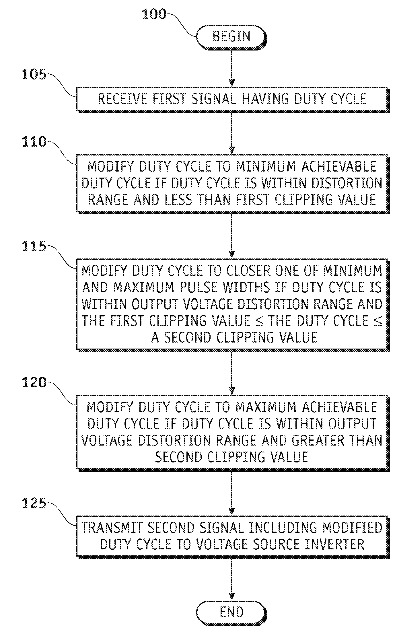
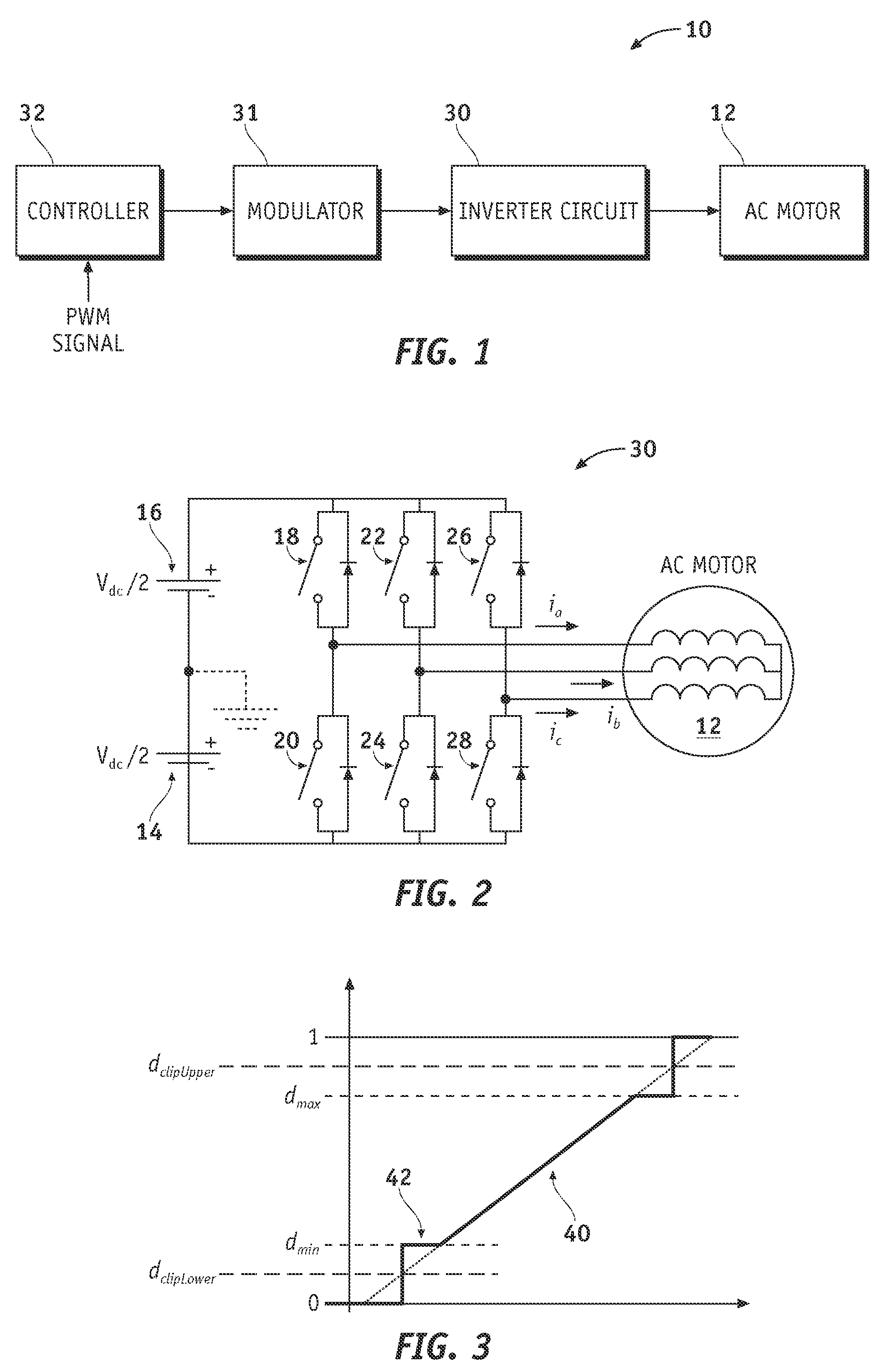
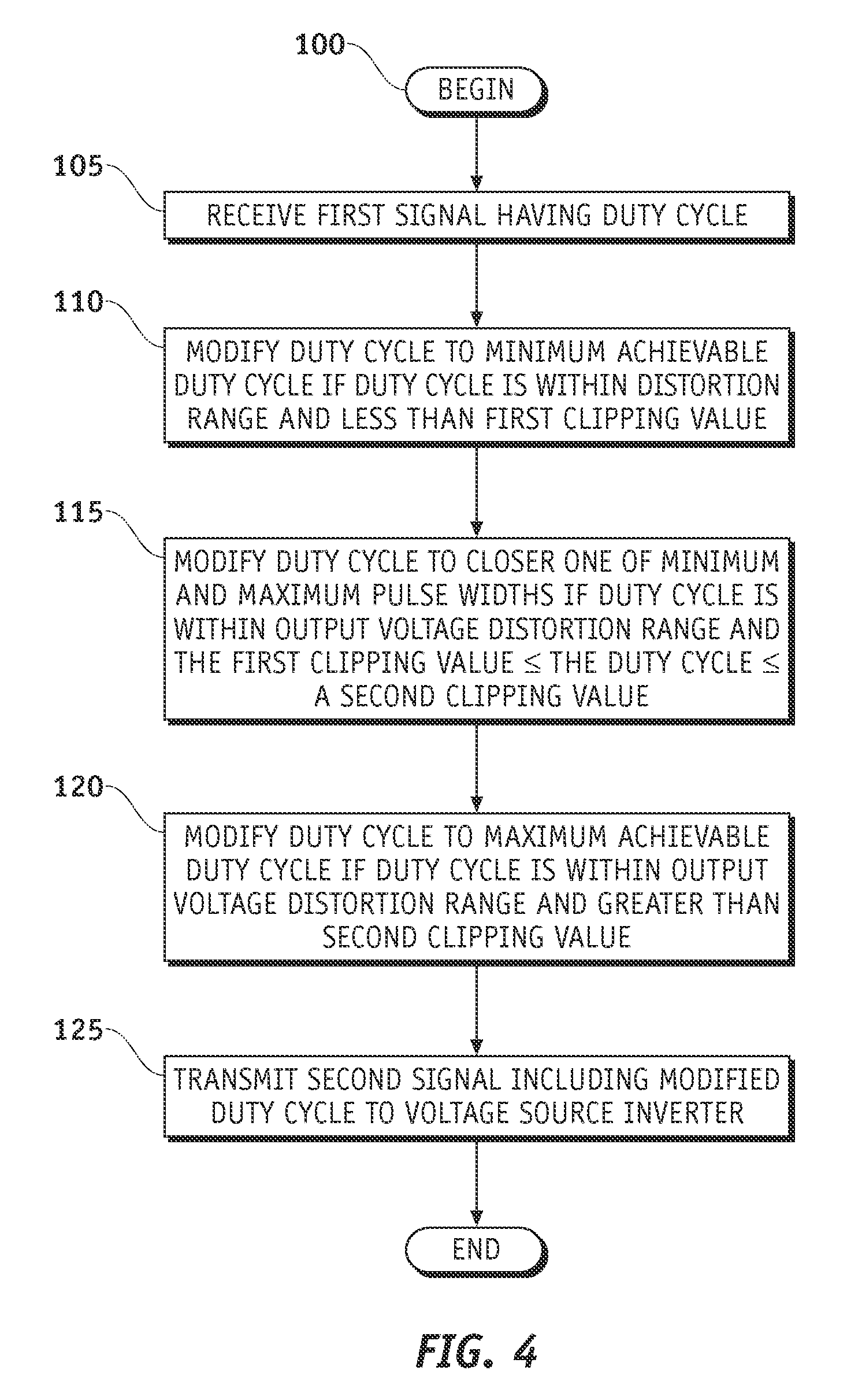
[0017]Referring to FIG. 1, a voltage source inverter system 10 is shown in accordance with an exemplary embodiment of the present invention. The voltage source inverter system 10 comprises a controller 32, a modulator 31 having an input coupled to an output of the controller 32, an inverter circuit 30 having an input coupled to an output of the modulator 31, and an alternating current (AC) motor 12 coupled to an output of the inverter circuit 30. Although the controller 32 and modulator 31 are shown and described as separate components of the voltage source inverter system 10, the controller 32 and modulator 31 may be combined into a singl...


PUM


Abstract

Methods and apparatus are provided for reducing voltage distortion effects at low speed operation in electric drives. The method comprises receiving a first signal having a duty cycle with a range between minimum and maximum achievable duty cycles, producing a second duty cycle based on the minimum achievable duty cycle if the duty cycle is within a distortion range and less than a first clipping value, producing a second duty cycle based on the closer of minimum and maximum pulse widths if the duty cycle is within the distortion range and between the first and a second clipping value, producing a second duty cycle based on the maximum achievable duty cycle if the duty cycle is within the distortion range and greater than the second clipping value, and transmitting a second signal to the voltage source inverter having the second duty cycle.

Description

TECHNICAL FIELD[0001]The present invention generally relates to voltage source inverters, and more particularly relates to apparatus and methods for controlling the output voltage component of a voltage source inverter in electric motors.BACKGROUND OF THE INVENTION[0002]An inverter controller may be used to control, among other things, a vehicle traction drive. In such cases, Discontinuous Pulse Width Modulation (DPWM) methods are commonly employed to control the fundamental output voltage component of voltage source inverters. For example, DPWM methods may be used to control the switching action of three-phase voltage source inverter. These three-phase voltage source inverters may in turn be used to control the phase currents of three-phase alternating current (AC) motors in electric drives.[0003]Ideally, the switch pairs in each phase leg of the three-phase voltage source inverter each operate in a complimentary fashion such that one switch is always “on” and the other switch is a...

Claims


Application Information

Patent Timeline
IPC IPC(8): H03K3/017
CPCH03K3/017H02M7/5395H02P27/06H02M1/0025
Inventor WELCHKO, BRIAN A.BAE, BONHOSCHULZ, STEVEN E.HITI, SILVA
Owner GM GLOBAL TECH OPERATIONS LLC
Why Eureka
Try Eureka