Discharge lamp control device and projector

Inactive Publication Date: 2008-08-21
SEIKO EPSON CORP
View PDF4 Cites 9 Cited by
  • Summary
  • Abstract
  • Description
  • Claims
  • Application Information

AI Technical Summary

Benefits of technology

[0008]a discharge lamp drive control section which performs constant current control so that a discharge lamp current that flows between electrodes of the discharge lamp becomes constant when a discharge lamp voltage applied between the electrodes of the discharge lamp is lower than a first voltage, and performs constant power control so that an amount of power supplied to the discharge lamp becomes constant when the discharge lamp voltag

Problems solved by technology

However, the electrodes of the discharge lamp may be melted due to the high discharge lamp current during constant current control.
The discharge lamp current during constant current control may be limited to prevent such a problem.
However, since the discharge lamp is turned off if the discharge lamp current is limited to a large extent, the discharge lamp current cannot be reduced to a large extent.
However, the electrodes of the discharge lamp are easily damaged due to a large change in current when the polarity of the discharge lamp current changes.
Therefore, the electrodes of the discharge lamp deteriorate when the drive frequency is too high, whereby the life of the discharge lamp decreases.

Method used


Image

  • Discharge lamp control device and projector
  • Discharge lamp control device and projector
  • Discharge lamp control device and projector

Examples


Embodiment Construction

[0022]The invention may provide a discharge lamp control device which prevents electrodes of a discharge lamp from being melted during constant current control after startup to extend the life of the discharge lamp, and a projector.

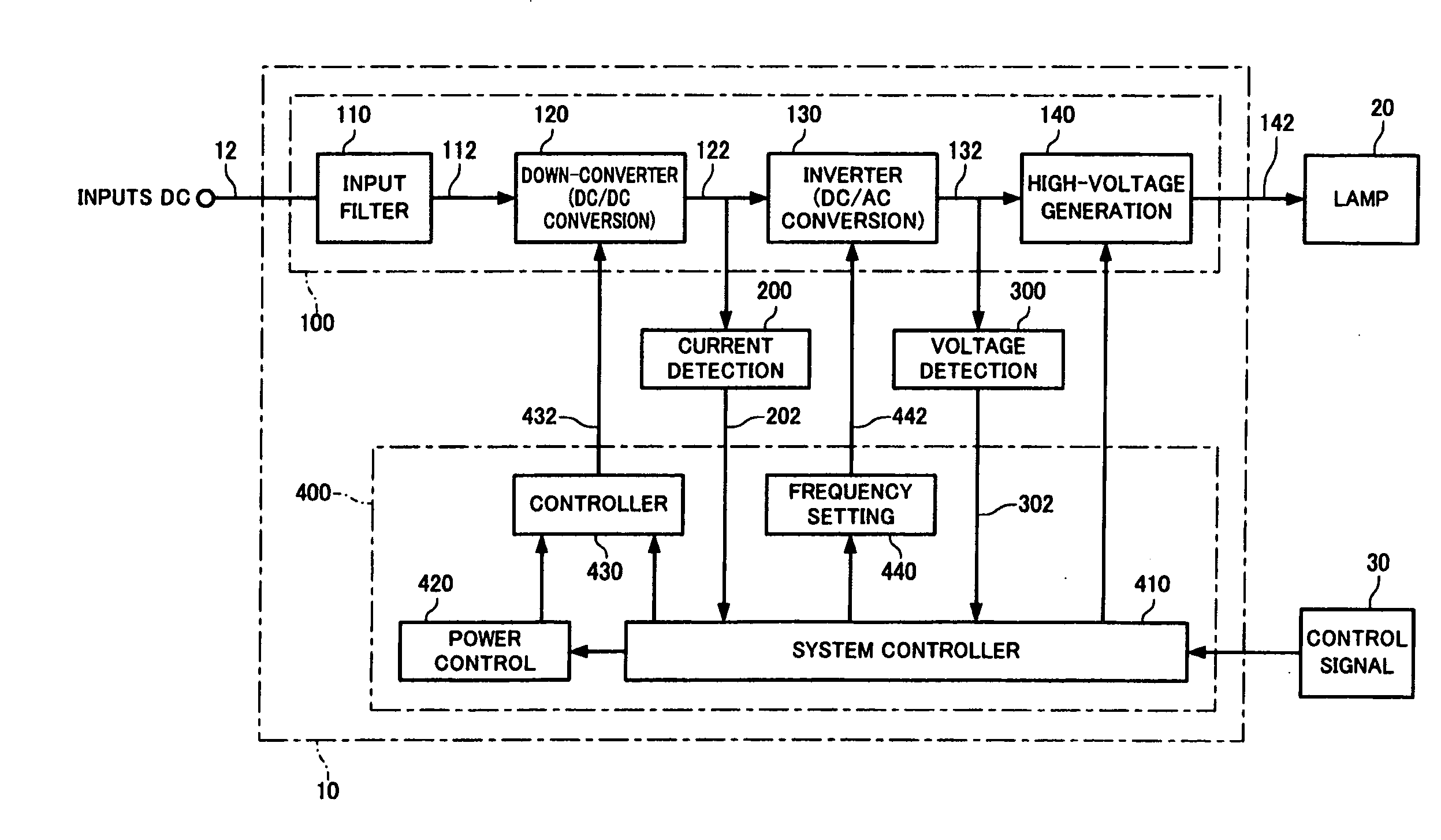
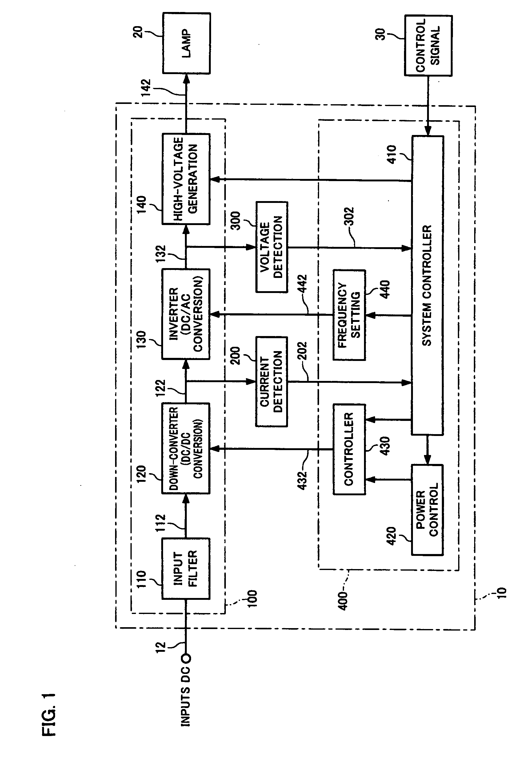
[0023](1) According to one embodiment of the invention, there is provided a discharge lamp control device which controls lighting of a discharge lamp, the discharge lamp control device comprising:

[0024]a discharge lamp driver section which drives the discharge lamp by outputting an alternating current having a given drive frequency to the discharge lamp; and

[0025]a discharge lamp drive control section which performs constant current control so that a discharge lamp current that flows between electrodes of the discharge lamp becomes constant when a discharge lamp voltage applied between the electrodes of the discharge lamp is lower than a first voltage, and performs constant power control so that an amount of power supplied to the discharge lamp becomes co...


PUM


Abstract

A discharge lamp control device includes: a discharge lamp driver section which drives a lamp; and a discharge lamp drive control section which performs constant current control so that a discharge lamp current that flows between electrodes of the lamp becomes constant when a discharge lamp voltage applied between the electrodes of the lamp is lower than a first voltage, and performs constant power control so that an amount of power supplied to the lamp becomes constant when the discharge lamp voltage is equal to or higher than the first voltage after the lamp has been lighted. The discharge lamp drive control section includes a discharge lamp drive frequency control section which causes the drive frequency when the discharge lamp voltage is lower than a second voltage which is equal to or lower than the first voltage to be lower than the drive frequency when the discharge lamp voltage is higher than the second voltage.

Description

[0001]Japanese Patent Application No. 2007-32057, filed on Feb. 13, 2007, is hereby incorporated by reference in its entirety.BACKGROUND OF THE INVENTION[0002]The present invention relates to a discharge lamp control device and a projector.[0003]A discharge lamp such as a high-pressure mercury lamp or a metal halide lamp is used as a light source of a projector. When lighting a discharge lamp, a high voltage of several tens of kilovolts is normally generated between electrodes of the discharge lamp in order to cause a dielectric breakdown between the electrodes of the discharge lamp to form a discharge path. The voltage (discharge lamp voltage) between the electrodes of the discharge lamp rapidly decreases immediately after the discharge lamp has been lighted. In order to heat the electrodes of the discharge lamp so that the discharge lamp voltage increases to a value near the rated voltage value, constant current control is performed so that a discharge lamp current which flows bet...

Claims


Application Information

Patent Timeline
IPC IPC(8): G03B21/14H05B41/26
CPCG03B21/14Y02B20/202H05B41/2887G03B21/2026Y02B20/00
Inventor KITAGAWA, KENICHI
Owner SEIKO EPSON CORP
Why Eureka
Try Eureka