
Reverse link power controlled repeater

a power control and repeater technology, applied in power management, wireless commuication services, frequency-division multiplex, etc., can solve problems such as gaps or holes in coverage areas, and the inability of some base stations to reach certain areas, and achieve the effect of reducing the number of repeaters

Inactive Publication Date: 2003-07-03
QUALCOMM INC
View PDF72 Cites 229 Cited by
  • Summary
  • Abstract
  • Description
  • Claims
  • Application Information

AI Technical Summary

Benefits of technology

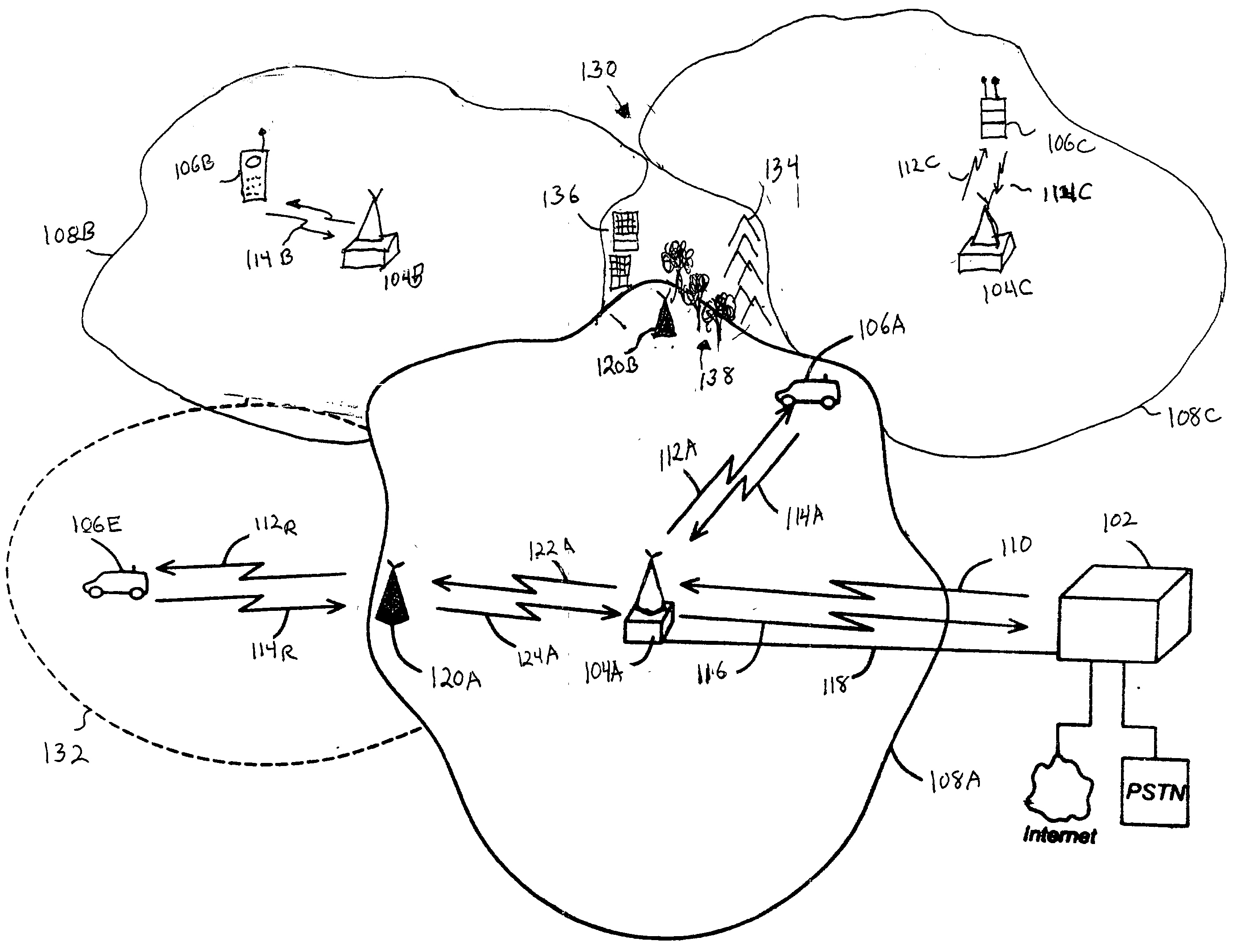
[0020] The method can further comprise periodically establishing a communication link between the wireless communication device and donor base station, and generating at least one power control signal based on information related to signal power determined during a duration of the communication link. This feature is especially useful when initially setting up a repeater, since the repeater can effectively "call in" to the base station and establish an appropriate power level without manual intervention.

Problems solved by technology

Unfortunately, as extensive as the total coverage areas of many wireless systems appear to be, providing service or coverage to many mobile stations is not without difficulties.
The deployment or positioning of base stations within a system may leave "gaps" or "holes" in the coverage area.
That is, the arrangement of the base stations, which can be dictated by various known system design criteria, economics, convenience, or local zoning restrictions, does not allow the signal coverage of some base stations to reach certain areas that are adjacent to or even surrounded by a group of base stations.
In addition, obstructions from geological features or man-made structures, may simply block signals in certain areas.
Base stations may also be considered too expensive to place in lower populated or more rural areas, leaving large areas simply uncovered.
Of course, any un-covered area or region means lost revenues for communication system operators or service providers.
However, the use of repeaters is not itself without problems in certain situations.
The use of repeaters is further hindered by environmental factors causing fluctuations in repeater gain, and in the thermal noise contributions by the repeater at the base station.
The phenomena stated above will result in fluctuations in the total amount of thermal noise at the base station, adversely affecting coverage as well as service in both the base station and repeater coverage areas.

Method used


Image

  • Reverse link power controlled repeater
  • Reverse link power controlled repeater
  • Reverse link power controlled repeater

Examples


Embodiment Construction

[0038] I. Introduction

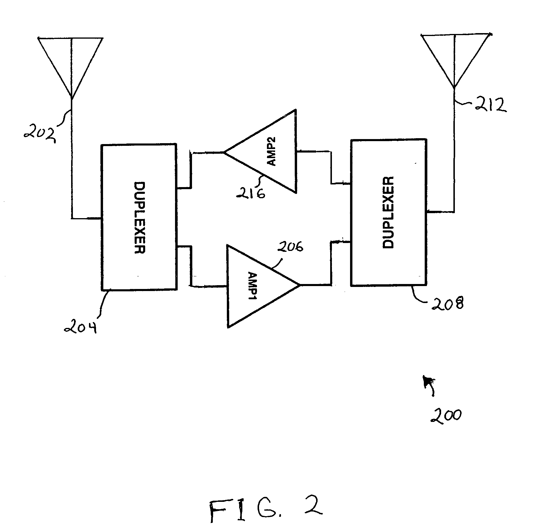
[0039] The present invention is a method and apparatus for controlling the gain and the transmission power of a repeater used in a wireless communication system by embedding a wireless communication device circuit within the repeater. The wireless communication device is power controlled or adjusted by base stations with which it communicates over a communication link held in common with repeater return link communication signals. One or more signals or commands generated by the wireless device interact with the repeater to cause the repeater to be gain and thus power controlled. As would be apparent to one skilled in the relevant art, the concept of the present invention can be applied to many types of communications systems where power control is used and there is a desire to reduce signal interference or degradation.

[0040] Embodiments of the invention are discussed in detail below. While specific steps, configurations and arrangements are discussed, it shoul...


PUM


Abstract

The invention provides a mechanism for automatically setting reverse link gain or power for a repeater (120) used in a communication system (100) through the use of the reverse link power control of a built-in wireless communications device. By embedding a wireless communication device (430, 630, 700) inside the repeater and injecting reverse link signals of the embedded device into the reverse link of the repeater (124A, 124B), the gain of the repeater is maintained relatively constant. The embedded WCD can also be activated on a periodic basis to make calls and utilize reverse link power-control to calibrate or re-calibrate the gain of the repeater, making it a power-controlled repeater.

Description

[0001] This application claims the benefit of U.S. Provisional Patent Application Serial No. 60 / 331,943, filed Nov. 20, 2001, pending, which application is incorporated herein by reference in its entirety.[0002] I. Field of the Invention[0003] The present invention relates generally to wireless communication systems, and more specifically, to a repeater for use in wireless communication systems having an embedded wireless communication device capable of interacting with base stations communicating with and through the repeater to affect control of repeater gain and output power.[0004] II. Related Art[0005] Wireless communication systems have developed a great deal in recent years and enjoy widespread use. There are presently many different types of wireless communication systems in use, including Cellular and Personal Communications Service (PCS) systems. Examples of known cellular systems include the cellular Analog Advanced Mobile Phone System (AMPS), and digital cellular systems ...

Claims


Application Information

Patent Timeline
IPC IPC(8): H04B7/005H04B1/00H04B7/155H04B7/26H04J13/00H04W52/08H04W52/14H04W52/46
CPCH04B7/15535H04B7/2606H04W52/46H04W52/14H04W52/146H04W52/08H04B7/14H04B7/155
Inventor DEAN, RICHARD F.
Owner QUALCOMM INC
Learn More