
Rodeo or riding device

Inactive Publication Date: 2008-08-21
CHUANG JIN CHEN +1
View PDF10 Cites 8 Cited by
  • Summary
  • Abstract
  • Description
  • Claims
  • Application Information

AI Technical Summary

Benefits of technology

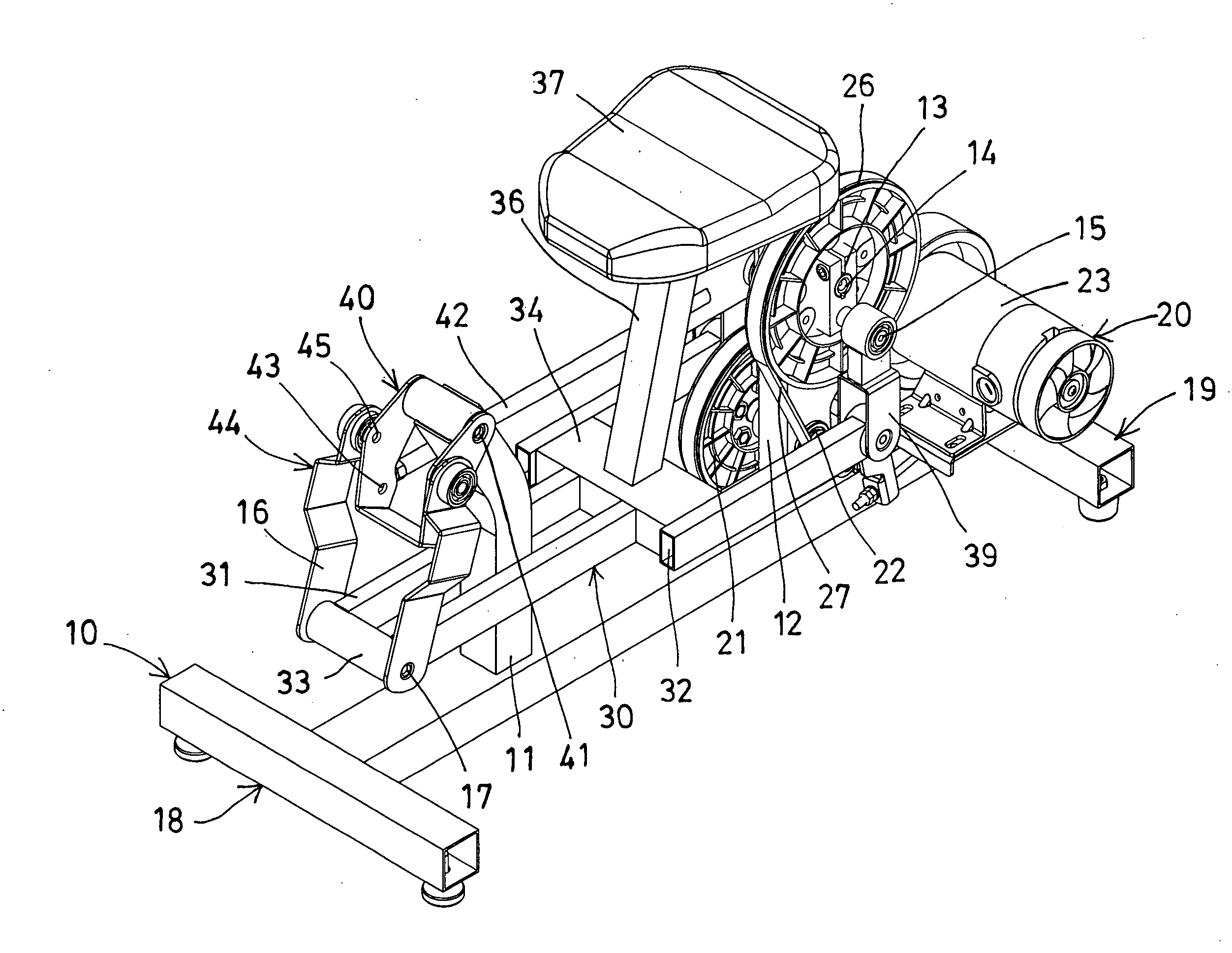
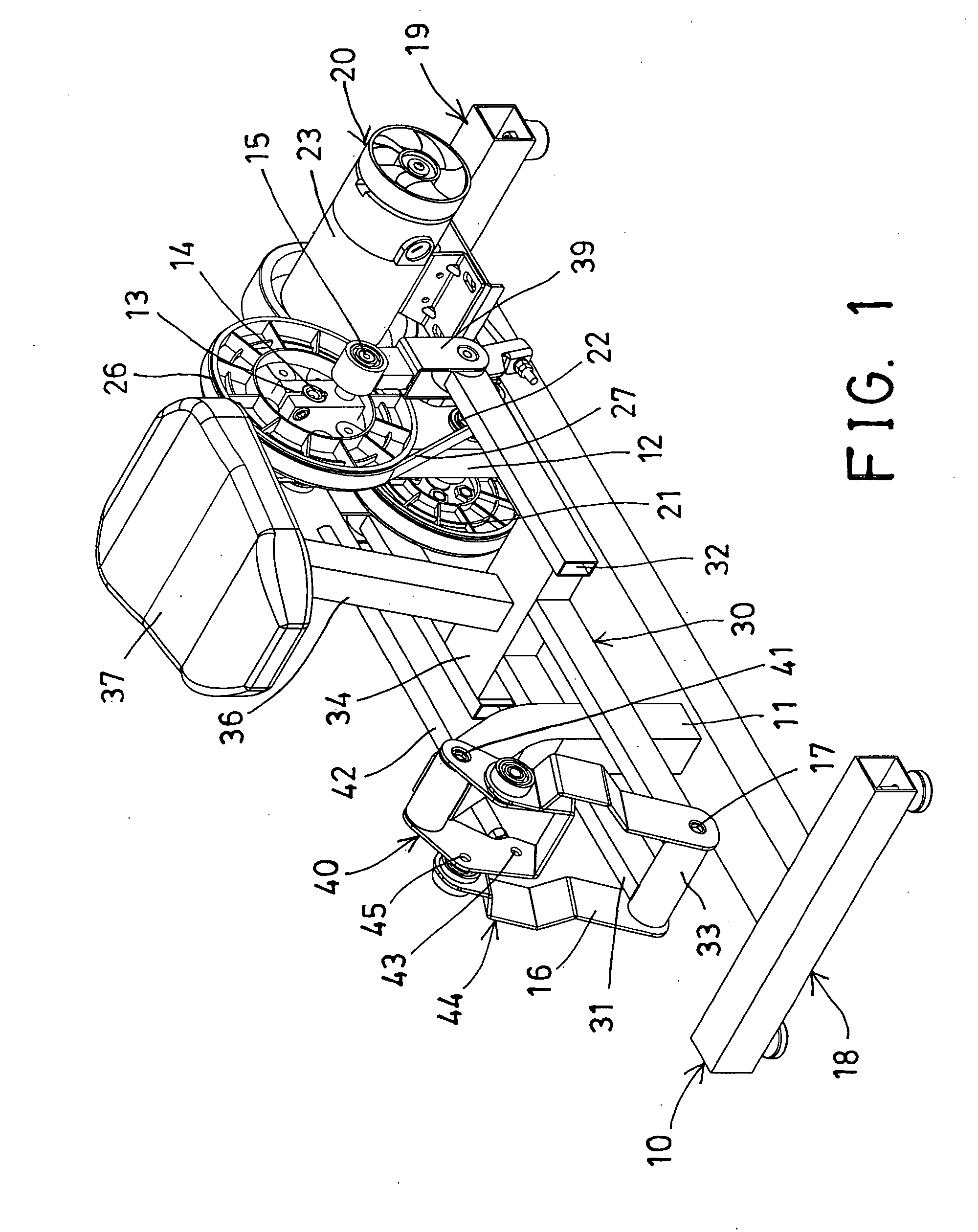
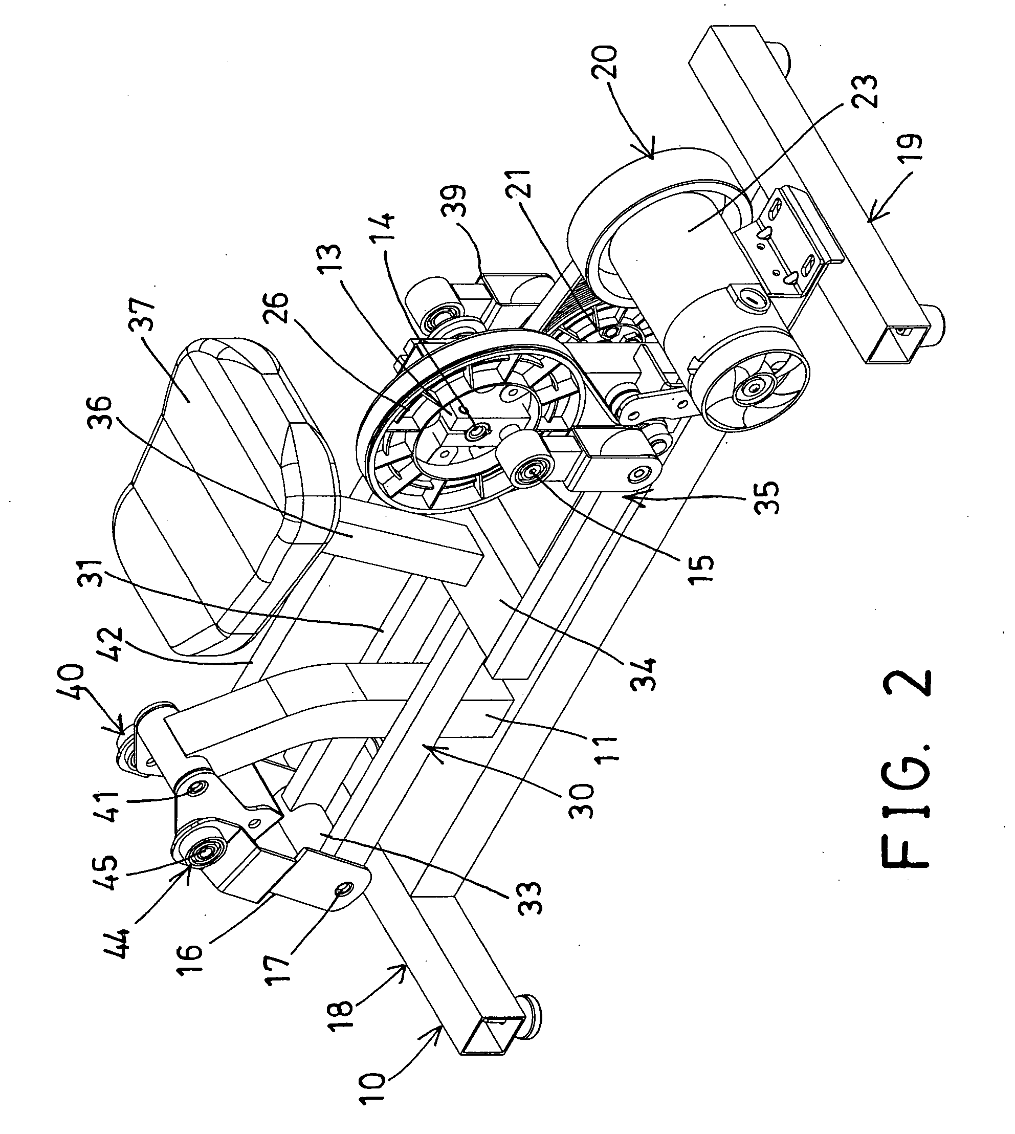
[0018]In accordance with one aspect of the invention, there is provided a riding device comprising a base including a column and a stud extended upwardly from the base, a crank device rotatably attached to the stud of the base with an axle and rotatable relative to the base in a cyclic and reciprocating action, a carrier including a front portion pivotally coupled to the column of the base for swinging relative to the base, and including a rear portion pivotally coupled to the crank device for moving cyclically relative to the base and for allowing the carrier to be moved in an elliptical and reciprocating action relative to the base by the crank device, a rider support supported on the carrier and moved in concert with the rider support for supporting a rider, and the carrier and the rider support being movable relative to the base in an elliptical and reciprocating action by the rider, and a motorized rotating device for driving or rotating the crank device relative to the base in the cyclic and reciprocating action in order to actuate the carrier and the rider support to move relative to the base in an elliptical and reciprocating action and for allowing the rider to conduct a riding or rodeo exercise.

Problems solved by technology

However, the rotating frame may only be rotated relative to the stationary base frame but not be moved relative to the stationary base frame in an elliptical and reciprocating action and also may not be moved relative to the stationary base frame in different moving stroke.
However, the fixed frame and the lower frame portion of the body portion may not be moved relative to the supporting ground or plane in an elliptical and reciprocating action and also may not be moved relative to the cranks and the swing arms of the drive mechanism in different moving stroke.
However, the seat plate is also solidly coupled to the drive mechanism with the cranks and the swing arms, such that the seat plate may not be moved relative to the cranks and the swing arms of the drive mechanism in an elliptical and reciprocating action and also may not be moved relative to the cranks and the swing arms of the drive mechanism in different moving stroke.

Method used


Image

  • Rodeo or riding device
  • Rodeo or riding device
  • Rodeo or riding device

Examples


Embodiment Construction

[0031]Referring to the drawings, and initially to FIGS. 1-5, a riding device in accordance with the present invention comprises a stationary base 10 including such as an I-shaped structure for increasing the stability of the base 10, and including a column 11 extended upwardly therefrom, such as extended upwardly from one end or the front portion 18 of the base 10, and including a stud 12 extended upwardly therefrom, such as extended upwardly from the other end or the rear portion 19 of the base 10, and including a crank device 13 or one or more (such as two) cranks 13 rotatably attached to or supported on the base 10, such as rotatably attached to the stud 12 with an axle 14 and rotatable relative to the base 10 in a cyclic and reciprocating action. A bearing or pivot pole 15 is attached to the free end portion of each of the cranks 13.

[0032]A carrier 30 is to be supported on the base 10 and is to be moved relative to the base 10 in an elliptical and reciprocating action, and inclu...


PUM


Abstract

A riding device includes a crank device rotatably attached to a base, and a rider support supported on a carrier and movable relative to the base for supporting a rider, the carrier has a front portion pivotally coupled to the base and a rear portion coupled to the cranks for moving cyclically relative to the base and for allowing the carrier to be moved in an elliptical and reciprocating action relative to the base by the crank device, and a motor or motorized rotating device for rotating the crank device relative to the base in the cyclic and reciprocating action to actuate the carrier and the rider support to move relative to the base in an elliptical and reciprocating action.

Description

[0001]The present invention is a continuation-in-part of U.S. patent application Ser. No. 11 / 654,732, filed 17 Jan. 2007, pending.BACKGROUND OF THE INVENTION[0002]1. Field of the Invention[0003]The present invention relates to a rodeo or riding device, and more particularly to a rodeo or riding device including a rider support or saddle supported on a carrier which is movable relative to a base by the user or rider or by an actuating device in an elliptical and reciprocating action for allowing the rider support and the rider also to be moved relative to the base in the elliptical and reciprocating action.[0004]2. Description of the Prior Art[0005]Typical riding devices or rodeo training devices comprise a rider support for supporting the users thereon, and a drive mechanism having a crank arm coupled to the rider support to drive the rider support and to simulate the bucking and / or spinning motions of a rodeo animal attempting to unseat its rider.[0006]For example, U.S. Pat. No. 3,...

Claims


Application Information

Patent Timeline
Patent Type & Authority Applications(United States)
IPC IPC(8): A63B69/04A63G19/20
CPCA63B69/04A63B69/0068
Inventor CHUANG, JIN CHENCHUANG, LUNG FEI
Owner CHUANG JIN CHEN
Learn More