Apparatus and method for monitoring a vehicle's surroundings

a technology for vehicles and surroundings, applied in the field of apparatus and a method for monitoring the surroundings of vehicles, can solve the problems of troublesome introduction of a stereo camera, increased cost of merely using one, and high calibration requirements of two cameras

Inactive Publication Date: 2008-08-28
SANYO ELECTRIC CO LTD
View PDF10 Cites 86 Cited by
  • Summary
  • Abstract
  • Description
  • Claims
  • Application Information

AI Technical Summary

Benefits of technology

[0017]For example, the vehicle surroundings monitoring apparatus is further provided with: a danger evaluator that evaluates the level of danger that the three-dimensional object poses to the vehicle; and a warning indicator that sends off a warning indication according to the evaluated level of danger. Here, the danger evaluator evaluates the level of danger based on one or more of: the result of recognizing whether the three-dimensional object is a stationary or moving object, the direction of movement of the three-dimensional object relative to the vehicle as detected on the two bird's-eye-view images having undergone the position adjustment; the speed of movement of the three-dimensional object relative to the vehicle as detected on the two bird's-eye-view images having undergone the position adjustment; the position of the three-dimensional object relative to the vehicle as detected on a bird's-eye-view image in which the three-dimensional object appears; and the size of the three-dimensional object as observed on a bird's-eye-view image in which the three-dimensional object appears.

Problems solved by technology

A stereo camera is composed of two cameras, and therefore merely using one incurs increased cost.
Moreover, a stereo camera needs adjustment of a baseline according to the distance to an obstacle, and this adjustment requires extremely high-accuracy calibration on two cameras.
Specifically, the fitting position and angle of two cameras need to be adjusted with extremely high accuracy, and this makes introduction of a stereo camera troublesome.
Moreover, vibration or the like of a vehicle may get the position and angle of cameras out of arrangement, making it high likely that, with use, the accuracy of obstacle detection deteriorates.
With the first conventional method, it is difficult to detect the distance of travel of the vehicle accurately; thus, the travel data obtained from the rudder angle sensor and the wheel speed sensor contains a comparatively large error.
As a result, a difference may arise even in a part of the compared images where no obstacle is actually present, leading to high likeliness to erroneously detect an obstacle.
Moreover, the use of dedicated sensors (the rudder angle sensor and the wheel speed sensor) incurs increased cost.
Likewise, using a dedicated sensor (the speed detecting device), the second conventional method suffers from similar inconveniences.

Method used


Image

  • Apparatus and method for monitoring a vehicle's surroundings
  • Apparatus and method for monitoring a vehicle's surroundings
  • Apparatus and method for monitoring a vehicle's surroundings

Examples


Embodiment Construction

[0031]Hereinafter, embodiments of the invention will be described specifically with reference to the accompanying drawings. Among the different drawings referred to in the course of description, the same parts are identified by common reference signs, and in principle no overlapping description of the same parts will be given.

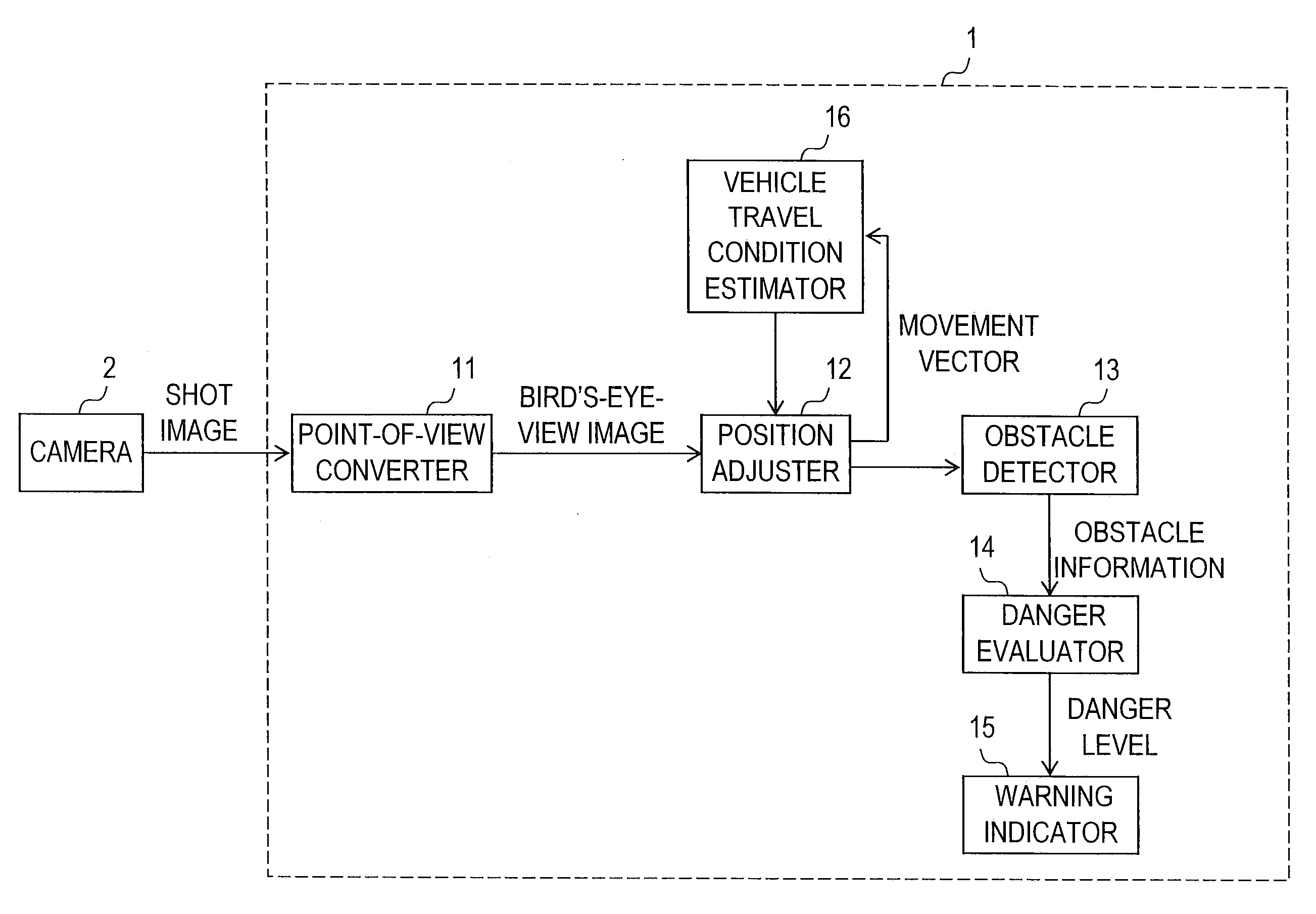
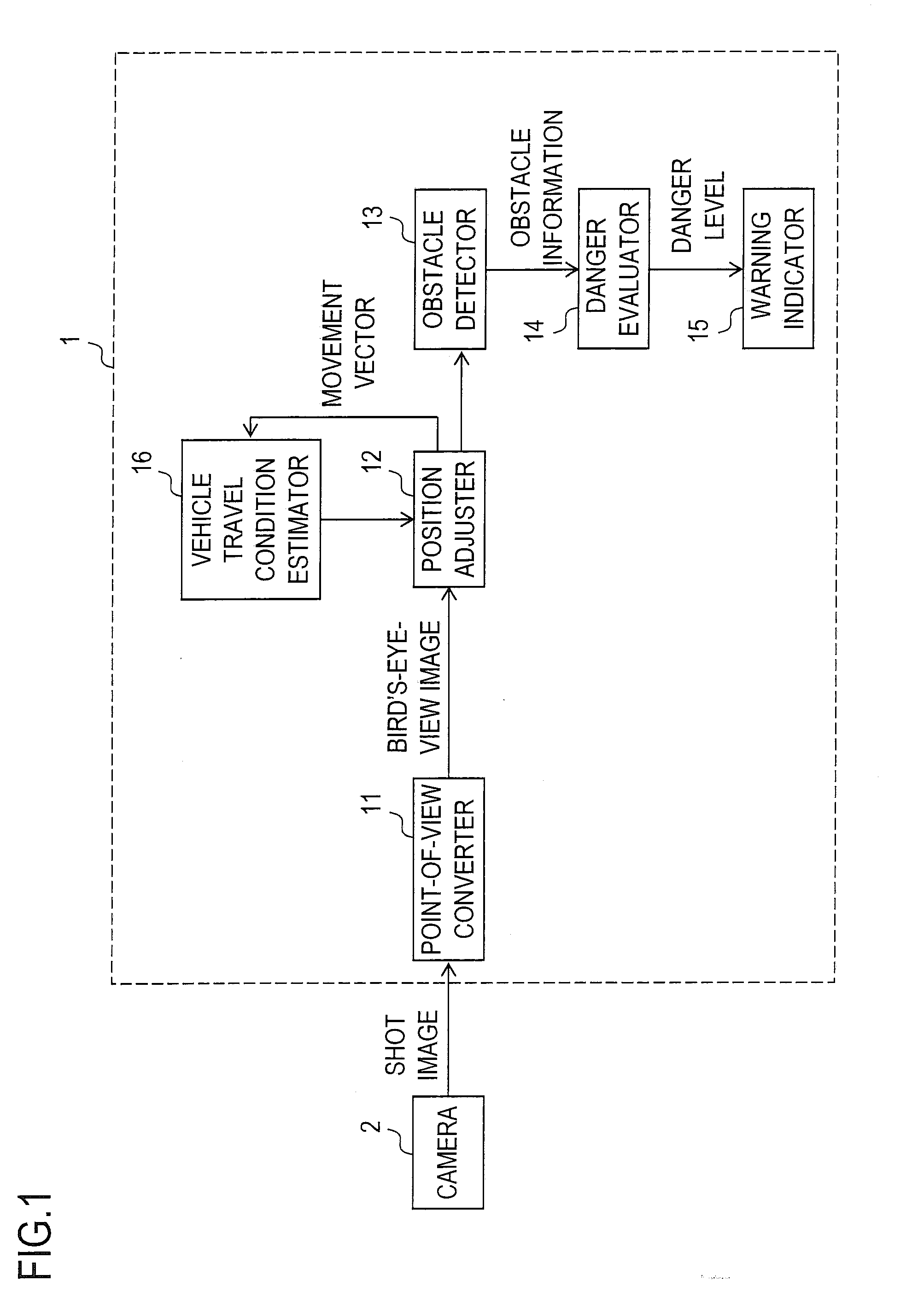
[0032]FIG. 1 is a functional block diagram of a vehicle surroundings monitoring apparatus 1 according to the invention. FIG. 2A is a side exterior view of a vehicle 3 equipped with the vehicle surroundings monitoring apparatus 1 and fitted with a camera 2, and FIG. 2B is a top exterior view of the vehicle 3. The vehicle 3 is assumed to be an automobile that either travels or stays at rest on the road surface. In FIG. 2B, a fan-shaped range 100 represents the shooting range of—the range shootable by—the camera 2 as seen from above. In the following description, it is assumed that what the term “road surface” denotes is the same as the ground, and that the term “...


PUM


Abstract

A vehicle surroundings monitoring apparatus has: a point-of-view converter that converts an image shot with a camera installed on a vehicle into a bird's-eye-view image through point-of-view conversion; a position adjuster that performs position adjustment between two bird's-eye-view images produced from two images shot at different time points, the position adjuster performing the position adjustment based on the two bird's-eye-view images; and a three-dimensional object detector that detects a three-dimensional object around the vehicle based on differences between the two bird's-eye-view images having undergone the position adjustment.

Description

[0001]This nonprovisional application claims priority under 35 U.S.C. § 119(a) on Patent Application No. 2007-049157 filed in Japan on Feb. 28, 2007, the entire contents of which are hereby incorporated by reference.BACKGROUND OF THE INVENTION[0002]1. Field of the Invention[0003]The present invention relates to an apparatus and a method for monitoring the surroundings of a vehicle by use of a camera.[0004]2. Description of Related Art[0005]One method of detecting an obstacle around a vehicle by use of a car-mounted camera employs a stereo camera. A stereo camera allows measurement of the distance to an obstacle. Thus, detection of a vehicle or pedestrian present frontward is often achieved by use of a stereo camera.[0006]A stereo camera is composed of two cameras, and therefore merely using one incurs increased cost. Moreover, a stereo camera needs adjustment of a baseline according to the distance to an obstacle, and this adjustment requires extremely high-accuracy calibration on t...

Claims


Application Information

Patent Timeline
Patent Type & Authority Applications(United States)
IPC IPC(8): G06K9/00H04N13/211H04N13/221
CPCB60R1/00B60R2300/607B60R2300/8093G06K9/00805H04N7/183H04N13/0221G06T7/20H04N13/221H04N13/211G06V20/58
Inventor HONGO, HITOSHI
Owner SANYO ELECTRIC CO LTD
Why Eureka
Try Eureka