Travel safety apparatus for vehicle

a safety apparatus and vehicle technology, applied in the field of vehicle safety apparatuses, can solve the problems of increasing complexity in the apparatus constitution and cost, affecting the detection reliability of imaging devices, and the center angle of the detection assurance range of radars is not easy to expand, so as to reduce the damage due to collisions

Inactive Publication Date: 2008-11-18
HONDA MOTOR CO LTD
View PDF3 Cites 46 Cited by
  • Summary
  • Abstract
  • Description
  • Claims
  • Application Information

AI Technical Summary

Benefits of technology

[0008]The present invention is made in view of the aforementioned circumstances, and an object thereof is to provide a travel safety apparatus for a vehicle which can perform early detection of an object around the vehicle and swiftly determine whether or not there is a possibility of a collision between the object and the vehicle with high accuracy without enlarging the detection assurance ranges of a plurality of detectors.
[0010]The travel safety apparatus for a vehicle of the present invention determines the possibility of a collision between the vehicle and an object when the object detected in the detection area of the first detector is identical to the object detected in the detection area of the second detector. The detection accuracy of the possibility of the collision can therefore be improved.
[0014]In this case, when the object detected in the sidelobe as the predetermined detection pattern and the object detected by the first detector exists within a predetermined distance, the travel safety apparatus determines that these two objects are identical. Therefore, even when the detection reliability of the sidelobe is lower than that of the second reliable detection area, the desired detection accuracy and the reliability of the detection result can be secured by combining the detection result of the first detector with the detection result in the sidelobe. As a result, in addition to the second reliable detection area, the sidelobe can be added to the second detection area and the travel safety apparatus can swiftly determine the possibility of collision between the object not only ahead of the vehicle but also approaching from the side of the vehicle with high accuracy without enlarging the second reliable detection area itself.
[0016]In this case, when the object detected in the remote area and the object detected by the second detector exists within a predetermined distance, the travel safety apparatus determines that these two objects are identical. Therefore, even when the detection reliability of the remote area is lower than that of the close area, the desired detection accuracy and the reliability of the detection result can be secured by combining the detection result of the second detector with the detection result in the remote area. As a result, in addition to the close area, the remote area can be added to the detection area of the first detector and the travel safety apparatus can swiftly determine the possibility of a collision between the object with high accuracy without enlarging the close area itself.
[0020]In this case, when only the millimeter-wave radar detects the object, the position detection accuracy is lower than when only the first detector such as a plurality of cameras detects the object or when both of the radar and the first detector detect the object. Then the travel safety apparatus determines the reliability of the collision determination result to be low and delays the operation timing of alarming and / or deceleration and the alarming and / or deceleration at improper timing can be prevented.
[0022]In this case, if the object is continuously detected only by the cameras for a predetermined period of time, the safety apparatus determines that the reliability of the collision determination result is higher than before the object is continuously detected. The safety apparatus can perform proper operations for avoiding the collision or reducing the damage due to the collision by setting a greater deceleration degree than that in normal operation.

Problems solved by technology

However, the center angle of the detection assurance range of the radar is not easy to enlarge, while that of the imaging device can be enlarged, for example by applying a wide-angle lens.
This is a cause of complexity in the apparatus constitution and rising cost.
In addition, since the imaging device has a shorter assured detecting distance than the radar, the detection reliability of the imaging device tends to decline in accordance with changes of conditions such as weather.

Method used


Image

  • Travel safety apparatus for vehicle
  • Travel safety apparatus for vehicle
  • Travel safety apparatus for vehicle

Examples


Embodiment Construction

[0032]A travel safety apparatus of an embodiment of the present invention shall be described with reference to the accompanying drawings.

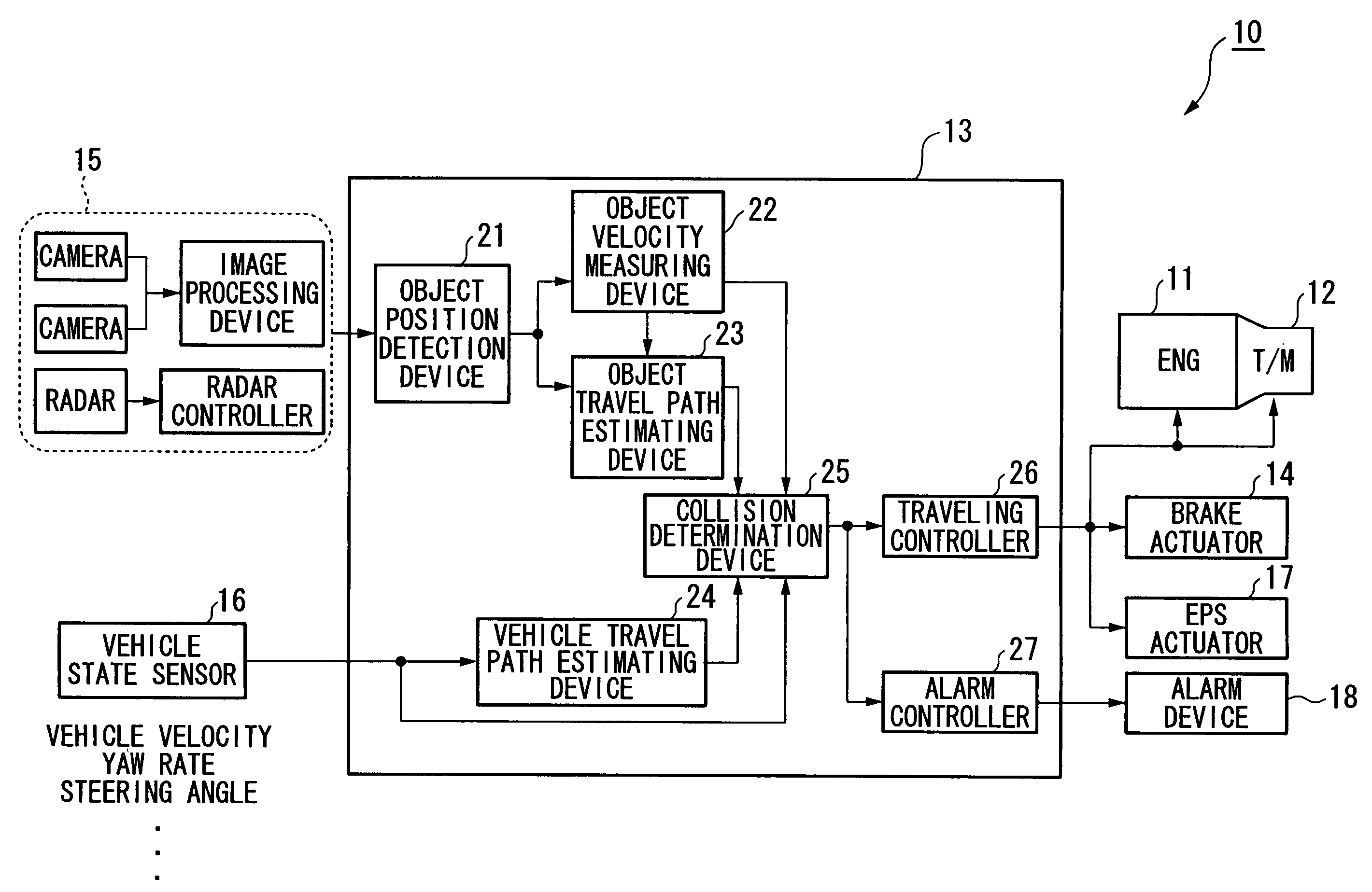
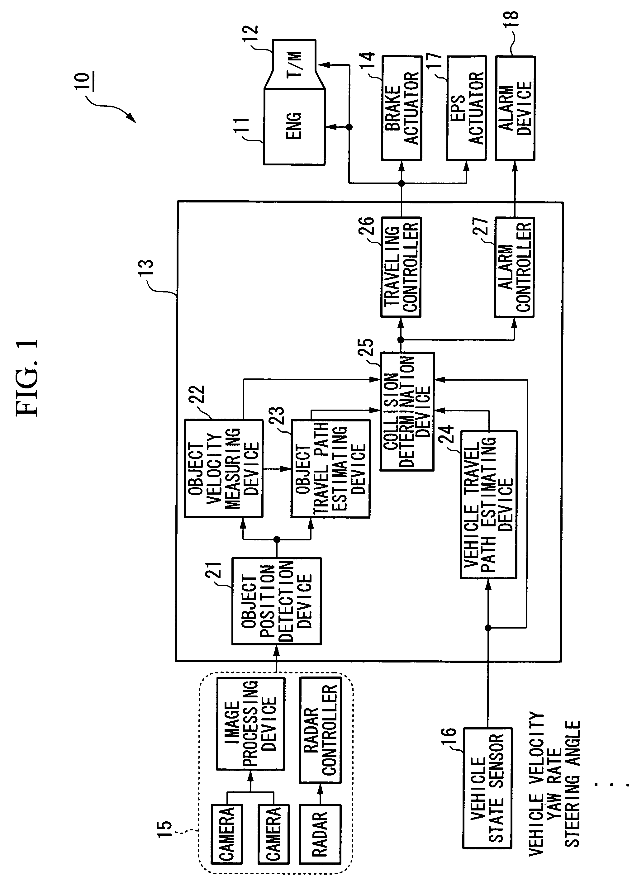
[0033]As shown in FIG. 1, a travel safety apparatus 10 of the present embodiment is mounted in a vehicle that transmits drive power from an internal-combustion engine 11 to the drive wheels of the vehicle by means of a transmission (T / M) 12 such as an automatic transmission (AT) or a continuously variable transmission (CVT), and has a constitution provided with a processing unit 13, a brake actuator 14, an external sensor 15, a vehicle state sensor 16, an EPS actuator 17, and an alarm device 18.

[0034]The external sensor 15 has a constitution provided with a pair of cameras (hereinafter, simply referred to as “cameras”) including a CCD camera or CMOS camera capable of performing imaging in the visible-light region and infrared region, an image processing device, a beam-scan type millimeter-wave radar, and a radar controller.

[0035]The image processin...


PUM


Abstract

A travel safety apparatus for a vehicle includes: a first object detector having a first detection area defined by a first detection angle; a second object detector having a second detection area defined by a second detection angle; a motion state determination unit; a collision determination unit determining whether there is possibility of collision of an object detected in at least one of the first detection area and the second detection area to the vehicle based on the motion state; a controller controlling the vehicle so that a collision is avoided; and an object identity determination unit determining whether the first object and the second object are identical, wherein when a first object detected in the first detection area and a second object detected in the second detection area are determined identical, the collision determination unit determines whether there is possibility of collision of the first object to the vehicle.

Description

BACKGROUND OF THE INVENTION[0001]1. Field of the Invention[0002]The present invention relates to a travel safety apparatus for a vehicle.[0003]Priority is claimed on Japanese Patent Application No. 2005-250886, filed Aug. 31, 2005 and Japanese Patent Application No. 2006-169106, filed Jun. 19, 2006, the contents of which are incorporated herein by reference.[0004]2. Description of Related Art[0005]An apparatus is known for detecting an object around a vehicle for preventing a collision between the object and the vehicle or for reducing damage due to the collision, the apparatus having a plurality of detectors such as a radar and an imaging device and recognizing the object based on detection results of the detectors (see, for example, Japanese Unexamined Patent Application, First Publication No. 2002-99907).[0006]In the apparatus of the aforementioned related art, a predetermined approximately sectorial detection assurance range in which a predetermined detecting accuracy is secured...

Claims


Application Information

Patent Timeline
Patent Type & Authority Patents(United States)
IPC IPC(8): G08G1/16B60R21/00B60R22/48B60T7/12B60W30/09B60W30/095B62D5/04B62D6/00B62D101/00B62D113/00B62D137/00
CPCB60Q9/008B60T7/22B60W10/18B60W30/095B60T2201/02B60T2201/022B60W30/08B60W30/09B60W50/14
Inventor KOIKE, HIROYUKISUGIMOTO, YOICHIURAI, YOSHIHIRO
Owner HONDA MOTOR CO LTD
Why Eureka
Try Eureka