Object detector

a technology of object detection and object detection, applied in the field of object detection, can solve the problems of not being able to accurately identify an object as a person, being a serious detriment to the smooth flow of traffic, and being unable to determine whether or not it is a pedestrian (a person)

Inactive Publication Date: 2007-07-19
ORMON CORP
View PDF6 Cites 52 Cited by
  • Summary
  • Abstract
  • Description
  • Claims
  • Application Information

AI Technical Summary

Benefits of technology

[0018]By an object detector of this invention, the position of an object detected by the object sensor and the image position of the face of a person obtained by the image sensor are compared and the object corresponding to the position of the image is identified as a person. Thus, it is possible to determine accurately whether the object detected by the sensor is a person (or an animal), independent of the outer shape of the person such as the clothing and to obtain the position and distance to the person.

Problems solved by technology

The device according to aforementioned Japanese Patent Publication Tokkai 7-270536 is capable of judging whether an object is a front going vehicle or a roadside structure but is not capable of determining whether or not it is a pedestrian (a person).
If a person is detected but if it is determined not as a person, there is a danger of contacting it, resulting in a traffic accident.
If a roadside structure or the like is detected but if it is erroneously identified as a person and the vehicle is suddenly stopped, it turns out to be a serious detriment to a smooth flow of traffic.
Although there exist technologies of using a camera to obtain an image of the front of an automobile and to identify an object within a specified area as a person if the shape of its image is nearly that of a person, the shape of a person does not always remain the same and it is not possible to accurately identity an object as a person.
If a person is wearing a heavy overcoat or carrying a briefcase so as to significantly alter his / her overall silhouette, it may be impossible to judge the image as that of a person.

Method used


Image

  • Object detector
  • Object detector
  • Object detector

Examples


Embodiment Construction

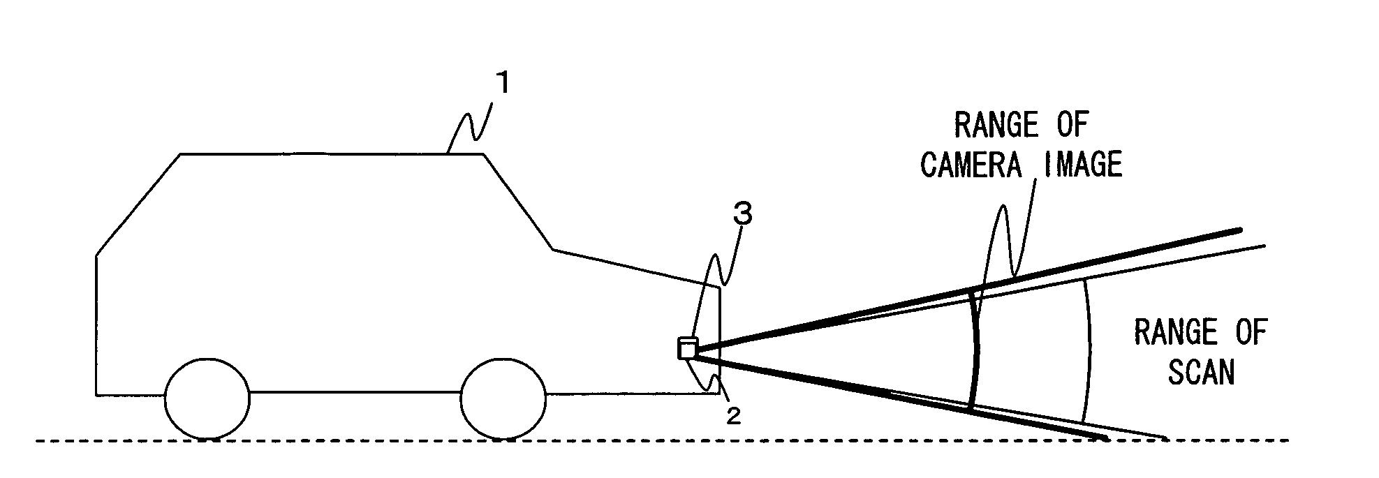
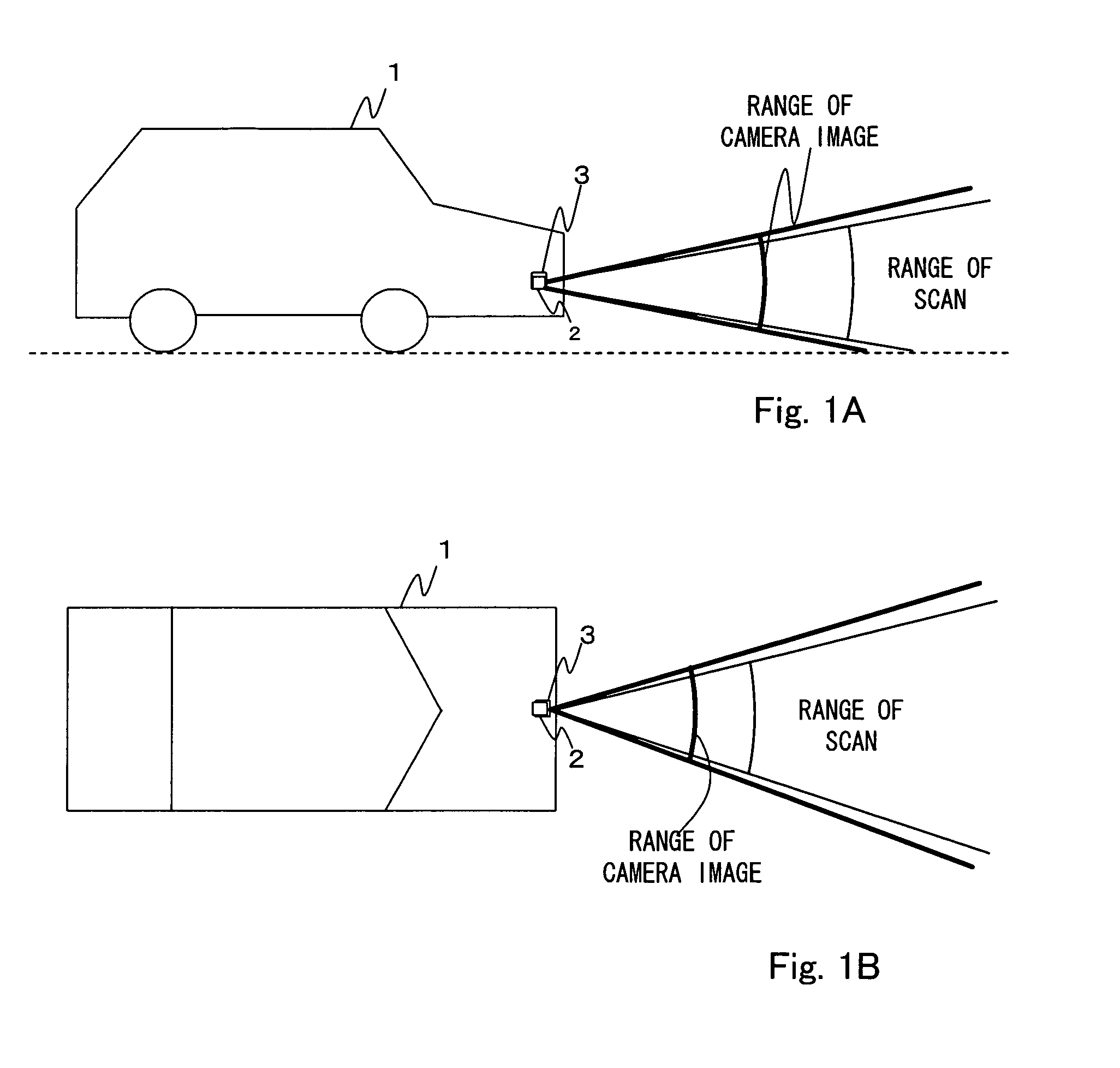
[0028]FIGS. 1A and 1B show an automobile 1 provided with a detector embodying this invention comprising a laser radar 2 (as an image sensor) and a camera 3 (as an object sensor) set at its front part. The laser radar 2 is for projecting near-infrared laser light to the front of the automobile 1 and detecting objects by receiving reflected light with a photodiode or the like. The camera 3 is for obtaining images of the front of the automobile 1 continuously or intermittently. Specified images are to be identified in such images.

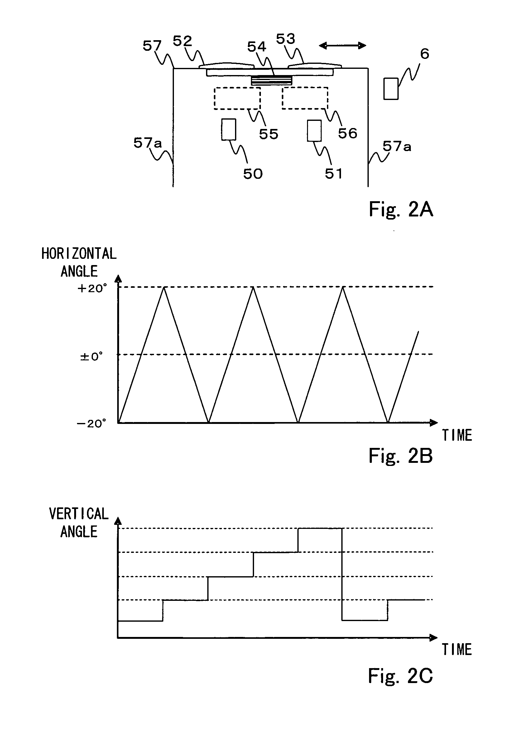
[0029]FIG. 1A is a side view of the automobile 1, and FIG. 1B is its plan view taken from above. The laser radar 2 is at the front end of the automobile 1 for projecting near-infrared laser light to the front of the automobile 1, the laser light being adjusted to scan horizontally over a specified angular range (such as by 200 to the left and to the right) and also vertically by a specified angle. The laser light may be arranged so as to change its vertical an...


PUM


Abstract

An object detector detects an object with a camera and calculates position data showing its direction and distance. A laser radar obtains an front image and recognizes an identified image in the front image. Coordinates of this identified image are calculated and converted to data indicating direction to the object. The identified image is correlated with the object detected by the laser radar and the correlated object is identified as an identified object. Position data of this correlated object are outputted as data on the identified object.

Description

[0001]This application claims priority on Japanese Patent Application 2006-007394 filed Jan. 16, 2006.BACKGROUND OF THE INVENTION[0002]This invention relates to an object detector capable of accurately distinguishing among the types of objects that are present in front of an automobile.[0003]In order to prevent traffic accidents involving automobiles, it is becoming a common practice in recent years to make use of optical distance measuring apparatus having a laser scanning device to use a near-infrared laser beam to scan the front and to detect the presence or absence of an object in front (such as a front going vehicle, an obstacle or a pedestrian) and to measure its distance by receiving its reflected light. Such distance measuring apparatus are being used for the cruising control for adjusting the speed of one's own vehicle according to the distance to the front going vehicle, as well as for the emergency stopping control for preventing contact with a pedestrian.[0004]In order t...

Claims


Application Information

Patent Timeline
Patent Type & Authority Applications(United States)
IPC IPC(8): G06K9/36G01S17/931G01S17/86
CPCG01S17/023G01S17/42G06K9/00805G06K9/00221G06K9/00228G01S17/936G01S17/86G01S17/931G06V40/16G06V40/161G06V20/58
Inventor ANDO, TANICHIFUJIOKA, RYOJI
Owner ORMON CORP
Why Eureka
Try Eureka