Light distribution pattern control using object detection and electrowetting lenses

a technology of object detection and light distribution pattern, applied in lighting support devices, instruments, lighting and heating apparatus, etc., can solve the problems of inconvenient and/or unsafe adjustments, slow response of the mechanical system to adjust these directional headlights, and waste of energy used to generate widespread ligh

Active Publication Date: 2012-11-15
APTIV TECH LTD
View PDF3 Cites 47 Cited by
  • Summary
  • Abstract
  • Description
  • Claims
  • Application Information

AI Technical Summary

Benefits of technology

[0004]In accordance with one embodiment of this invention, a system for controlling a light distribution pattern is provided. The system includes a light source, an electrowetting lens, an object detector, and a controller. The light source is operable to emit light. The electrowetting lens is operable to vary a light distribution pattern of light from the light source into an area. The object detector is configured to indicate a location of an object. The controller is configured to operate the electrowetting lens in order to control the light distribution pattern into the area based on the location of the object indicated by the object detector.
[0005]In another embodiment of the present invention, a controller for a light distribution pattern control system configured to illuminate an area is provided. The controller includes an output and an input. The output is configured for outputting a control signal to an electrowetting lens operable to vary a light distribution pattern of light fro...

Problems solved by technology

Some light sources provide illumination that may be unnecessarily widespread and so some of the energy used to generate that widespread light is wasted.
Reflectors, shrouds, and/or glass lenses may be used to adjust the light distribution pattern of light from widespread to focused, but making such adjustments may be inconvenient and/or unsa...

Method used


Image

  • Light distribution pattern control using object detection and electrowetting lenses
  • Light distribution pattern control using object detection and electrowetting lenses
  • Light distribution pattern control using object detection and electrowetting lenses

Examples


Embodiment Construction

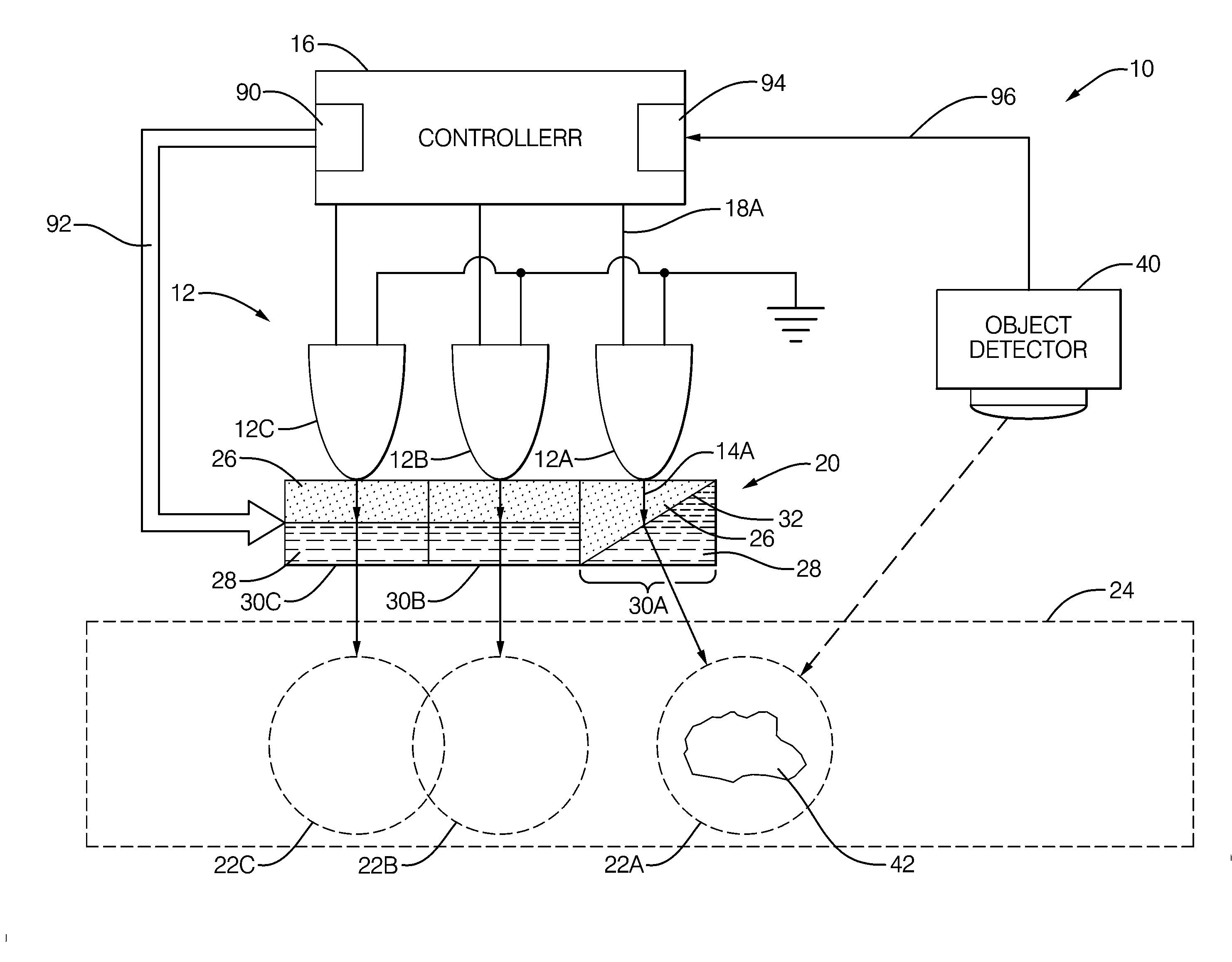
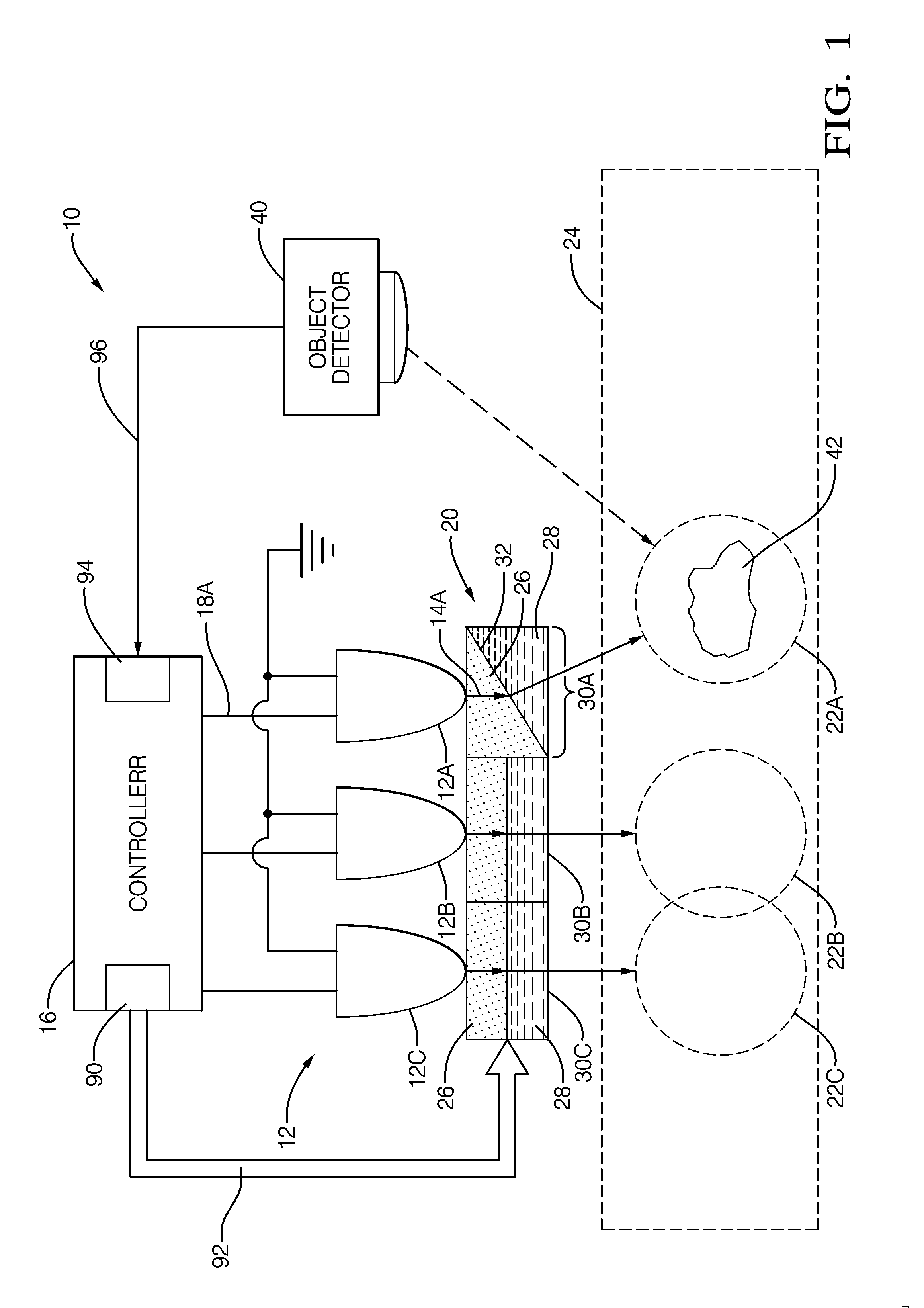
[0013]FIG. 1 illustrates a non-limiting example of a system 10 for controlling a light distribution pattern. The system 10 generally includes a light source 12A operable to emit light as indicated by arrow 14A, hereafter sometimes light 14A. The light source 12A may be any kind source of light, for example incandescent, fluorescent, or a light emitting diode (LED). Preferably, light emitted by the light source 12A is directed or focused in a particular direction as suggested by the arrow 14A; however an omnidirectional type light source may be used. The light source 12A may be connected to a controller 16, or the like, via a light source connection 18A so that the controller 16 can operate the light source to be OFF, and so not emit light, or ON, and so emit light.

[0014]The system 10 may include an electrowetting lens 20 operable to vary a light distribution pattern 22A of light from the light source 12A into an area 24. In general, electrowetting lenses, also known as liquid lenses...


PUM


Abstract

A system, controller, and method for controlling a light distribution pattern. A light source and an electrowetting lens cooperate to vary a light distribution pattern of light from the light source. An object detector is used by a controller determine the location of an object and operate the electrowetting lens in order to control the light distribution pattern based on the location of the object. The electrowetting lens provides for faster redirecting of light toward an object when compared to mechanical based system. The light source may be an array of light emitting diodes to provide a reliable, energy efficient source of light.

Description

TECHNICAL FIELD OF INVENTION[0001]The invention generally relates to controlling a light distribution pattern of light from a light source, and more particularly relates to controlling that light distribution pattern based on an indication of an object in or near an area potentially illuminated by the light.BACKGROUND OF INVENTION[0002]It is desirable to have sufficient illumination of an object or location being viewed by a person. Some light sources provide illumination that may be unnecessarily widespread and so some of the energy used to generate that widespread light is wasted. One solution is to provide focused light source instead of, or in addition to, the widespread light source a light so the type of light desired can be selected. Reflectors, shrouds, and / or glass lenses may be used to adjust the light distribution pattern of light from widespread to focused, but making such adjustments may be inconvenient and / or unsafe depending on the situation.[0003]Some vehicle manufac...

Claims


Application Information

Patent Timeline
IPC IPC(8): G02B26/02
CPCB60Q1/085B60Q2300/45F21S48/1731F21V5/02F21V23/0478F21S48/125G02B3/14G02B26/005G02B26/0875F21S8/04F21S48/1225F21Y2101/02F21Y2115/10F21S41/285F21S41/25F21S41/645
Inventor KUHLMAN, FREDERICK F.SARMA, DWADASI H.R.LUKMANI, NASSER
Owner APTIV TECH LTD
Why Eureka
Try Eureka