Device for cooling electrical equipment in a turbomachine

Inactive Publication Date: 2008-09-04
HISPANO SUIZA SA
View PDF15 Cites 39 Cited by
  • Summary
  • Abstract
  • Description
  • Claims
  • Application Information

AI Technical Summary

Benefits of technology

[0004]A particular object of the invention is to provide a s

Problems solved by technology

Known cooling devices generally comprise means for circulating a cooling fluid such as oil, fuel, or air, and they are often bulky and complex to

Method used


Image

  • Device for cooling electrical equipment in a turbomachine
  • Device for cooling electrical equipment in a turbomachine

Examples


Embodiment Construction

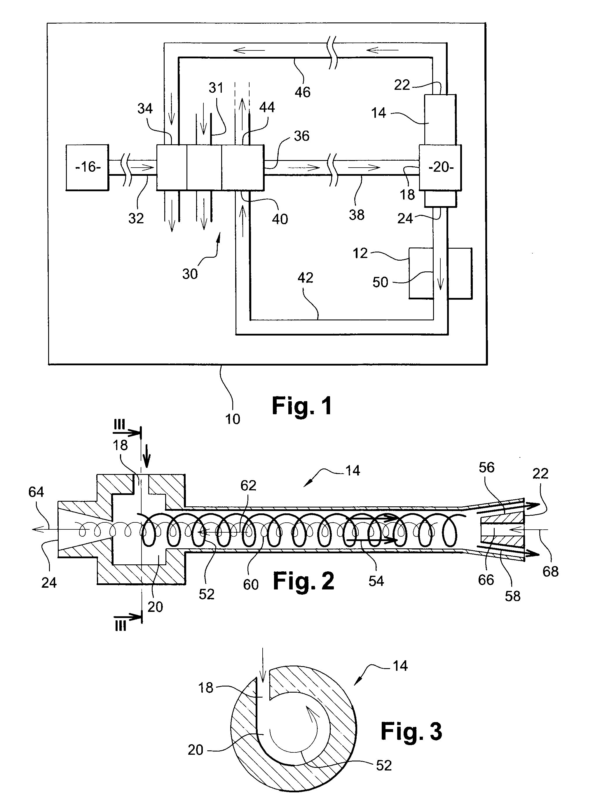
[0018]FIG. 1 is a highly diagrammatic representation of the device of the invention for cooling electrical or electronic equipment 12 in a turbomachine 10, the device comprising a vortex tube 14 or Ranque tube fed with pressurized air that is taken from an element 16 of the turbomachine, said element 16 being constituted for example by a fan duct, a low pressure or high pressure compressor, or an auxiliary compressor of smaller size driven by an accessory gearbox of the turbomachine.

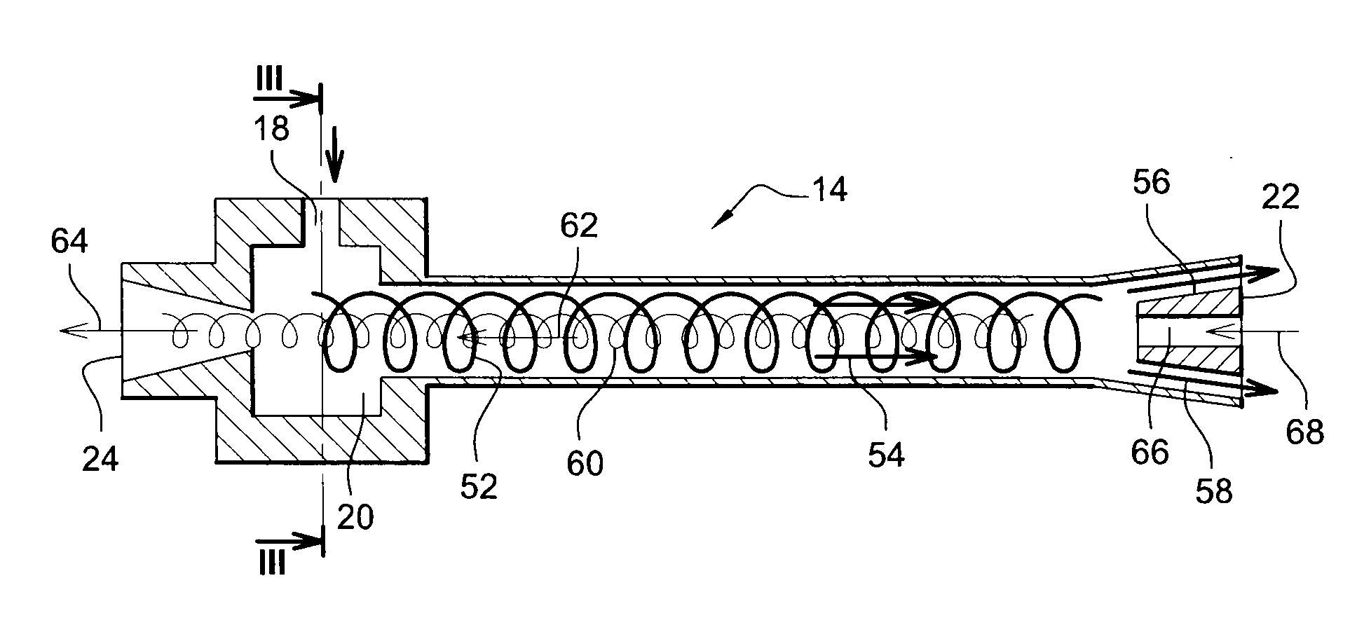
[0019]The vortex tube 14 has an inlet 18 opening out into a chamber 20 formed between the ends of the tube, the tube having a hot air outlet 22 at one of its ends and a cold air outlet 24 at its other end. The well-known operation of the vortex tube is described in detail below with reference to FIGS. 2 and 3.

[0020]In the example shown, the cooling device further comprises a heat exchanger 30 having one or more stages comprising a primary circuit with an inlet 32 connected to means for taking air from th...


PUM


Abstract

A device for cooling electrical or electronic equipment in a turbomachine, such as a unit for controlling actuators for variable-geometry elements, the device comprising at least one vortex tube having an inlet connected to means for feeding pressurized air taken from an element of the turbomachine, and a cold air outlet connected to means for cooling the electrical equipment.

Description

[0001]The present invention relates to a device for cooling electrical or electronic equipment in a turbomachine.BACKGROUND OF THE INVENTION[0002]A turbomachine includes a certain number of pieces of electrical or electronic equipment, such as units for controlling actuators of variable-geometry elements, which pieces of equipment generate a large amount of heat that needs to be removed in order to maintain acceptable temperatures for the electrical equipment and also for certain elements of the turbomachine situated in the vicinity of said equipment.[0003]Known cooling devices generally comprise means for circulating a cooling fluid such as oil, fuel, or air, and they are often bulky and complex to implement. Furthermore, those devices present risks of leakage, and they require regular maintenance operations, which are lengthy and expensive.OBJECTS AND SUMMARY OF THE INVENTION[0004]A particular object of the invention is to provide a solution to those problems that is effective and...

Claims


Application Information

Patent Timeline
IPC IPC(8): F25B9/04
CPCF25B9/04H01L2924/0002H01L2924/00
Inventor DE WERGIFOSSE, ERICFICHEFET, HUGUETTE
Owner HISPANO SUIZA SA
Why Eureka
Try Eureka