Fuel pressure sensor diagnosing device and method

a fuel pressure sensor and diagnostic device technology, applied in the direction of electric control, machines/engines, instruments, etc., can solve the problems of difficult to specify which component parts, difficult to detect which components, and significant time-consuming for vehicle inspection, so as to facilitate the reliable detection of fuel pressure sensor failur

Inactive Publication Date: 2008-09-04
ISUZU MOTORS LTD
View PDF3 Cites 22 Cited by
  • Summary
  • Abstract
  • Description
  • Claims
  • Application Information

AI Technical Summary

Benefits of technology

[0015]It is an object of the present invention to provide a fuel pressure sensor diagnosing device and method that, in resolving the aforementioned problems, facilitates the reliable detection of fuel pressure sensor failure.

Problems solved by technology

As a result, when characteristic shift of a common rail pressure sensor occurs, irrespective of the injector and so on being instructed by the control computer to generate an identical target injection quantity, the actual injection quantity changes due to the abnormal common rail pressure and, as the desired fuel injection quantity cannot be produced, leads to exhaust emission and performance deterioration.
However, the following problems are inherent to the diagnosing method described above.
First, in the conventional method for indirectly diagnosing a common rail pressure sensor, because the diagnosis is performed while the supply pump is being actuated, aside from simple disconnection / short-circuiting failure, both failure of the common rail pressure sensor and failure of the supply pump must be considered as causes of a lack of equivalence between a target common rail pressure and common rail sensor detected pressure and, as a result, it is difficult to specify which component part is the cause thereof and vehicle inspection takes a significant amount of time.
For this reason, there is a concern that when a driver switches ON the ignition key and immediately thereafter actuates the start causing the engine to rotate, and that this will preclude a diagnosis from being performed.
On the other hand, when the shifted characteristics are offset to the low side, there is a possibility that that the engine will be started and run in an abnormal state and, in turn, a concern that a diagnosis will not be able to be performed.

Method used


Image

  • Fuel pressure sensor diagnosing device and method
  • Fuel pressure sensor diagnosing device and method
  • Fuel pressure sensor diagnosing device and method

Examples


Embodiment Construction

[0026]The “fuel pressure sensor diagnosing device and method” described by the specification, claims and drawings of this application is described in Japanese Patent Application No. 2007-51788.

[0027]A preferred embodiment of the present invention will be hereinafter described with reference to the attached drawings.

[0028]The fuel pressure sensor diagnosing device (hereinafter the diagnosing device) of this embodiment has application in a diesel engine in which a high-pressure fuel is held in a common rail for injection through an injector, for example, in a diesel engine mounted in an automotive vehicle.

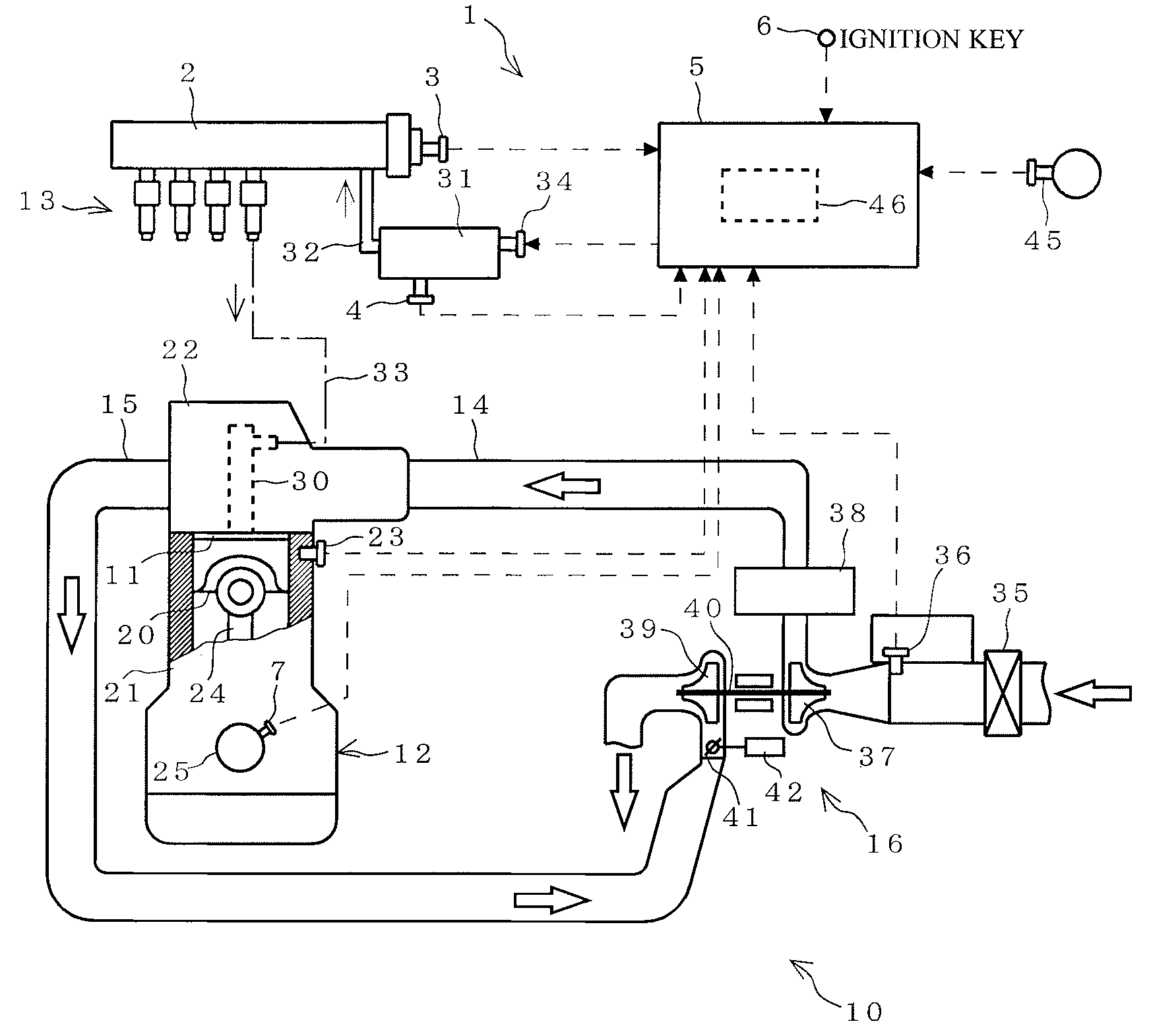
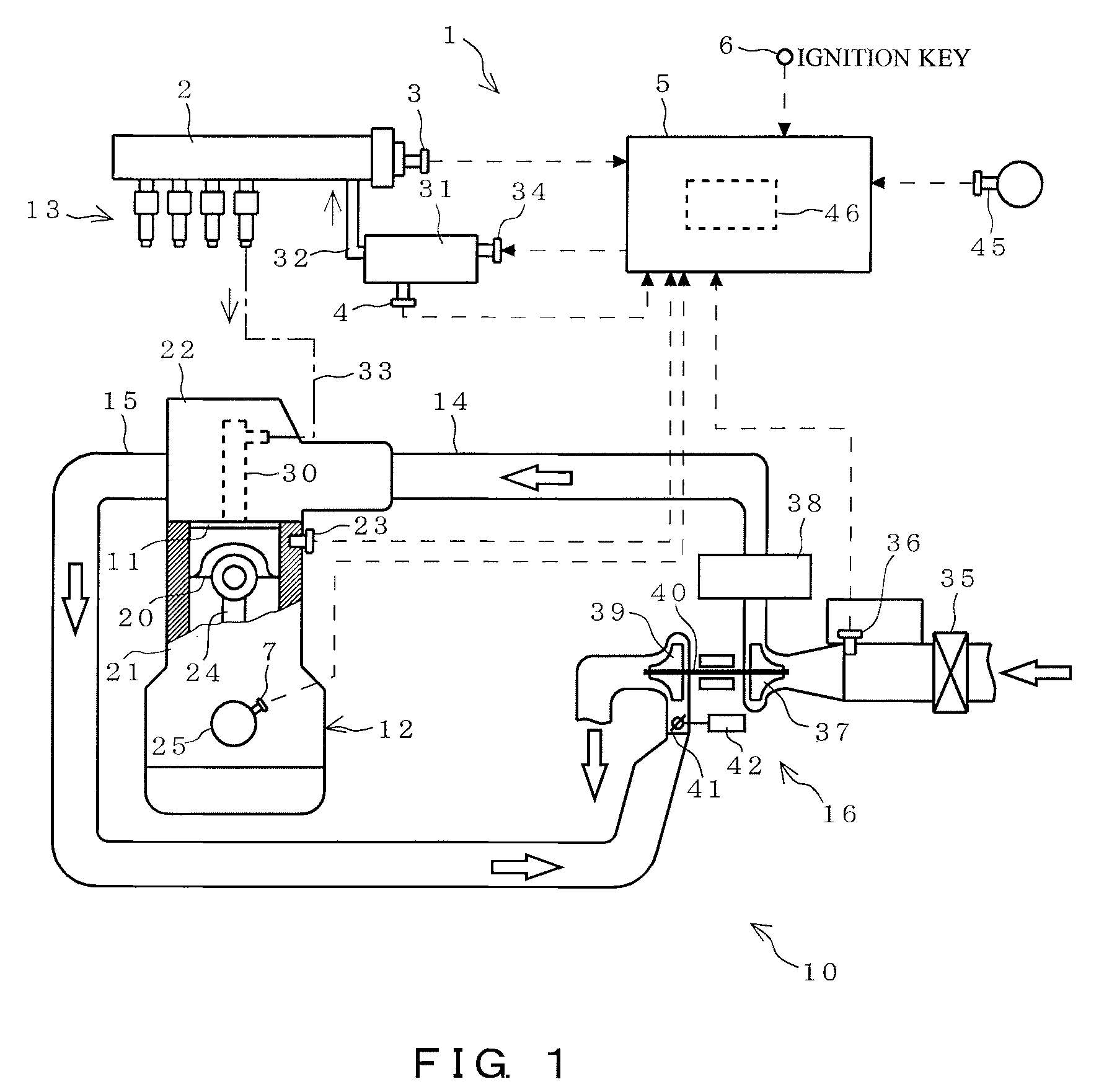
[0029]The general structure of an engine in which the diagnosing device of the embodiment has application will be described with reference to FIG. 1.

[0030]An engine 10 comprises an engine main body 12 in which a combustion chamber 11 is formed, an pressure-intensifying type fuel injection control device 13 for injecting and supplying fuel to the engine main body 12 to the combustion ...


PUM


Abstract

A fuel pressure sensor diagnosing device for diagnosing a fuel pressure sensor for detecting pressure in a common rail in which a high-pressure fuel to be supplied to an engine is accumulated, the device comprising: fuel temperature detection means for detecting fuel temperature; and failure determination means, provided with the fuel temperature detection means for detecting fuel temperature via subsequent to stopping of the engine, for obtaining a resting and stabilization time between when the pressure in the common rail drops and when the pressure stabilizes on the basis of this detected fuel temperature, detecting a stabilized fuel pressure via the fuel pressure sensor subsequent to lapse of the resting and stabilization time, and determining a failure of the fuel pressure sensor when the detected stabilized fuel pressure exceeds a predetermined upper limit threshold value or is less than a predetermined lower limit threshold value.

Description

CROSS REFERENCE TO RELATED APPLICATION [0001]This application claims priority to Japanese Patent Application No. 2007-51788 (filed Mar. 1, 2007), the details of which are incorporated herein by reference.BACKGROUND OF THE INVENTION[0002]1. Field of the Invention[0003]The present invention relates to a device and method for diagnosing a fuel pressure sensor for detecting common rail fuel pressure.[0004]2. Description of the Related Art[0005]A control computer of pressure-accumulating type fuel injection control devices comprising a so-called common rail uses a regulating valve to execute a feedback control on the discharge quantity of an injection pump (supply pump) based on fuel pressure sensor (common rail pressure sensor) information obtained while the engine is running in such a way as to ensure a target common rail pressure value established in accordance with the engine revolutions and load and so on is produced. To that end, a common rail pressure sensor serves a very importan...

Claims


Application Information

Patent Timeline
Patent Type & Authority Applications(United States)
IPC IPC(8): G01M15/04F02M69/46
CPCF02D41/042F02D41/222F02D41/3809F02M2200/24F02D2200/0606F02M63/0225F02D2200/0602
Inventor HANARI, AKIRAYOMOGIDA, KOUICHIROU
Owner ISUZU MOTORS LTD
Why Eureka
Try Eureka