Method of detecting damage to an engine bearing

a technology of engine bearings and detection methods, applied in the direction of fluid pressure measurement by mechanical elements, solid vibration measurement, machine part testing, etc., can solve the problems of difficult to discern vibration levels and not always detect damage, and achieve the effect of reducing such drawbacks

Active Publication Date: 2008-09-18
SN DETUDE & DE CONSTR DE MOTEURS DAVIATION S N E C M A
View PDF6 Cites 36 Cited by
  • Summary
  • Abstract
  • Description
  • Claims
  • Application Information

AI Technical Summary

Benefits of technology

[0006]The main object of the present invention is thus to mitigate such drawbacks by proposing a method that enables damage to a bearing providing rotary support to at least one rotary shaft of an engine to be detected reliably.

Problems solved by technology

Nevertheless, tests on damaged bearings have shown that damage is not always detected using such a method.
The measurements from vibration sensors are “polluted” at high speeds of operation of the turbomachine by an environment that is naturally vibrating (combustion noise, noise caused by aerodynamic flow, numerous harmonics of the speeds of rotation of the high and low pressure shafts, etc.), which makes it difficult to discern the vibration levels that are characteristic of damage.

Method used


Image

  • Method of detecting damage to an engine bearing
  • Method of detecting damage to an engine bearing
  • Method of detecting damage to an engine bearing

Examples


Embodiment Construction

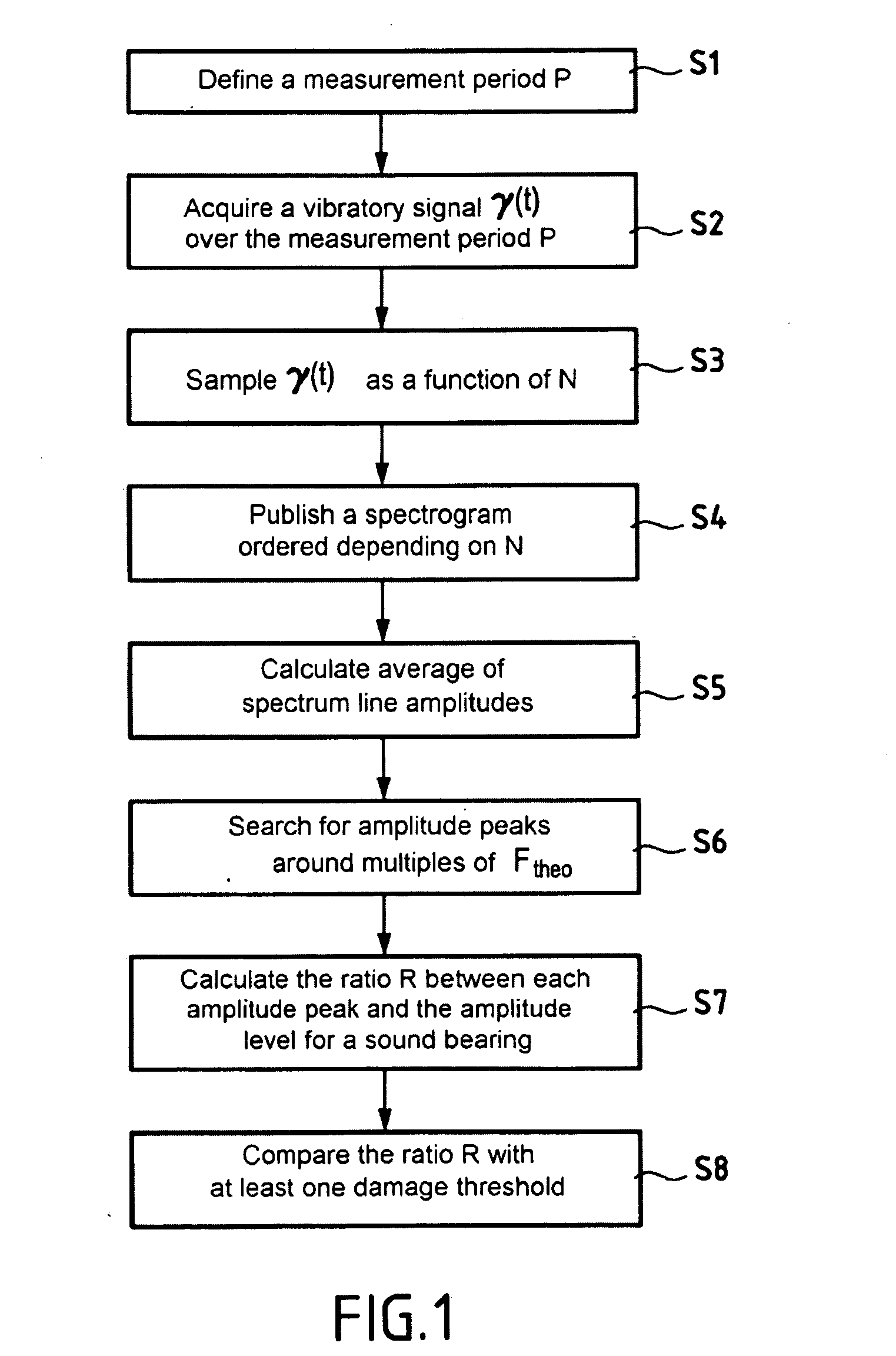
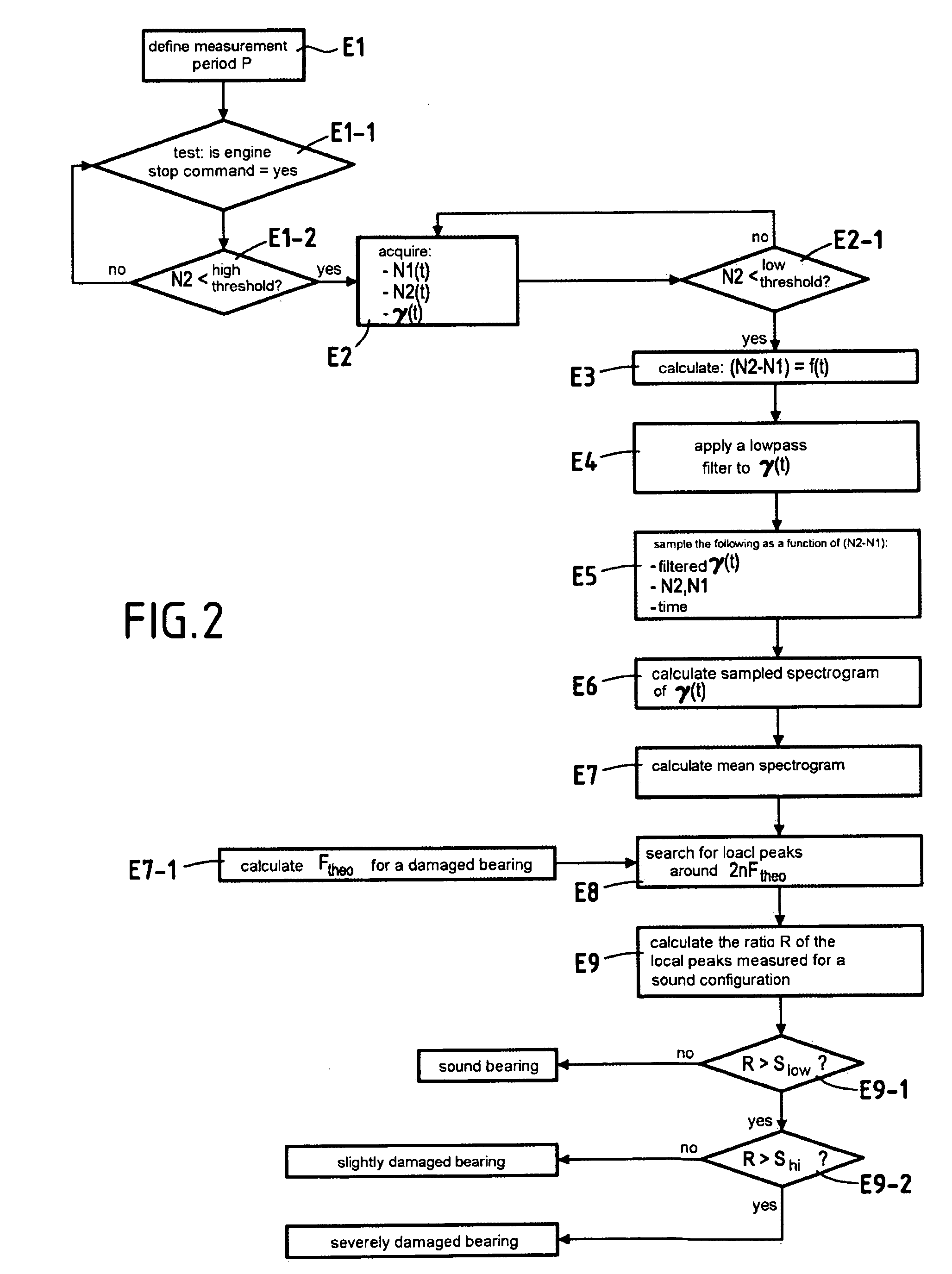
[0025]Reference is made to FIG. 1 which shows the steps making up a method in accordance with the invention for detecting damage to a rolling bearing providing rotary support for at least one rotary shaft of an engine.

[0026]In general, the invention applies to any type of engine that possesses at least one rotary shaft and at least one rolling bearing and that presents renewable activity at low speed (starting stage, stopping stage, idling, low-speed cycling, etc.). Amongst such engines, mention can be made, for example, of airplane or helicopter gas turbine engines (referred to as turbomachines), terrestrial gas turbines, gearboxes, axle engines, etc.

[0027]The principle on which the invention is based is that the frequency that results from bearing damage is proportional to the speed of rotation of the rotary shaft supported by the bearing. The assumption is that this frequency will be transmitted to an acceleration sensor via the components of the engine that are themselves vibrat...


PUM


Abstract

The invention relates to a method of detecting damage in a bearing supporting at least one rotary shaft of an engine in rotation, the method consisting in: defining a measurement period corresponding to a range of speeds of rotation of the shaft during renewable activity at low speeds of operation of the engine; acquiring over the entire measurement period a vibratory signal representative of acceleration of components of the engine; sampling the vibratory signal as a function of the speed of rotation of the shaft during the measurement period; transforming the sampled vibratory signal into a frequency signal to obtain frequency spectrum lines as a function of the speed of rotation of the shaft; calculating the mean of the amplitudes of the spectrum lines; determining amplitude peaks around multiples of the theoretical frequency of a damaged roller; calculating the ratio between each amplitude peak and the amplitude level determined for a sound bearing; and comparing the ratio that is obtained with at least one predetermined damage threshold.

Description

BACKGROUND OF THE INVENTION[0001]The present invention relates to the general field of monitoring wear in a bearing providing rotary support for at least one rotary shaft of an engine, for example an inter-shaft bearing in an aviation turbomachine.[0002]Rolling bearings (ball bearings or roller bearings) are commonly used in the field of aviation, in particular for providing rotary support for the shafts of the high and low pressure spools of a turbomachine.[0003]The wear of turbomachine bearings needs to be monitored in order to detect early any damage to a bearing, and thus anticipate breakage or serious malfunction of the bearing.[0004]One of the known methods of monitoring wear in a turbomachine bearing is based on the principle whereby the frequency that results from damage to the bearing is proportional to the speed of rotation of the shafts or shaft supported by the bearing, and said frequency propagates in the form of vibration through the components of the turbomachine. Thu...

Claims


Application Information

Patent Timeline
Patent Type & Authority Applications(United States)
IPC IPC(8): G01M7/02F02K9/38G01M13/04
CPCG01M13/045
Inventor BLANCHARD, SERGEGRIFFATON, JULIEN
Owner SN DETUDE & DE CONSTR DE MOTEURS DAVIATION S N E C M A
Why Eureka
Try Eureka