Material characterization with model based sensors

a sensor and model technology, applied in the field of non-destructive materials characterization, can solve the problems of poor conductivity between the fastener and the skin layer, and the range of conductivity of alodine fasteners, so as to improve the reliability of crack detection, and improve the effect of conductivity

Inactive Publication Date: 2007-03-29
JENTEK SENSORS
View PDF22 Cites 36 Cited by
  • Summary
  • Abstract
  • Description
  • Claims
  • Application Information

AI Technical Summary

Benefits of technology

[0008] In an embodiment, hidden cracks in a layered material and near fasteners are detected by scanning a sensor over the test material surface and acquiring data at multiple excitation frequencies. Often, the material layers are metal, such as an aircraft skin, so that the sensor can use a magnetic field to interrogate the material and cracks form beneath the exposed surface of the material. A high frequency measurement is performed to determine the material properties above or shallower than the crack, which can include the sensor lift-off from the material surface, the fastener type, and the quality of the conduction between the fastener and the test material layers. In particular, anodized fasteners tend to have poor conductivity between the fastener and the skin layers while alodine fasteners can have a range of conductivity, from poor to good, depending upon the quality of the fastener installation. A lower frequency measurement provides sensitivity to the presence and properties of a crack. Taking the difference between the high and low frequency responses tends to highlight the response associated with the crack. To improve the crack detection reliability, the net response is filtered through comparison to a reference or signature scan for a crack, which is in turn compared to a threshold value to determine the likelihood that a crack is present. The high frequency response can also be used to adjust the threshold value, again to increase the reliability of crack detection. In an embodiment, the sensor has at least two rows of parallel sensing elements to facilitate imaging over wider areas during the inspection. Each row of sensing elements is positioned to either side of a linear drive conductor which provides different levels of sensitivity to cracks on either side of the fastener. The responses can be combined together to create a single response image that can show the presence of cracks on either side of the fastener. To further improve the crack detection reliability, in another embodiment, a library of signature responses, determined empirically or from computer simulation, are used and the lift-off is used to select or determine an appropriate signature response for the filtering operation.
[0009] In one embodiment, engine disk slots are inspected without having to remove the disk itself from the engine. This involves removing the blades from the engine disk and mounting near the disk a fixture that contains a flexible sensor or sensor array that can be inserted into the disk slot and scanned over the slot material surface. Since these disks are commonly superalloy metals, the sensor uses a magnetic field, like an eddy-current sensor, to assess the material condition. Typically, an encoder or some other means is used to monitor sensor position inside the slot so that the measured responses can be readily formed into an image and locations of any suspect areas in the slot can be readily determined. In an embodiment, a pressurizable support such as a balloon is placed behind the sensor and expanded after the sensor is in the slot in order to bring the sensor closer to the material surface and to reduce mechanical stresses on the sensor itself from the insertion process. In another embodiment, the fixture also contains a guide that can be actuated to rotate the disk or even pass into a second slot to maintain the alignment of the sensor with the slot and the rotation rate. In yet another embodiment, the sensor response is converted into effective material properties, such as an electrical conductivity or lift-off. When a lift-off is determined, the lift-off can be used to determine the quality of the inspection, for example by ensuring that it is within reasonable bounds.
[0010] In another embodiment, the interfacial condition between a coating and a conducting substrate. This is accomplished by placing a magnetic field or eddy-current sensor on the opposite side of the substrate from the coating and converting measured sensor responses into at least one model parameter that is correlated with the interfacial condition. In an embodiment, the interfacial condition is the residual stress. In another, the model parameter is magnetic permeability. In other embodiments, the coating is a metal bond coat which has a magnetic relative permeability greater than 1 or the bond coat properties are selected to enhance sensitivity to the residual stress between an insulating outer coating or top coat and the substrate. In an embodiment, a model is used to estimate multiple parameters for the coating and substrate. One embodiment has the sensor scanned along the outside surface of an aircraft engine, which facilitates the creation of images of property or parameter values that can be used to detect damage, such as a disbond. Another embodiment has the sensor mounted to an outside surface of the engine so that the sensor remains in place during service and can be used to monitor wear or detect damage on the inside of the engine. Furthermore, multiple frequencies can be used with precomputed databases of responses to determine multiple properties for the material layers, including magnetic permeability of one of the material layers and sensor lift-off.

Problems solved by technology

In particular, anodized fasteners tend to have poor conductivity between the fastener and the skin layers while alodine fasteners can have a range of conductivity, from poor to good, depending upon the quality of the fastener installation.

Method used


Image

  • Material characterization with model based sensors
  • Material characterization with model based sensors
  • Material characterization with model based sensors

Examples


Embodiment Construction

[0037] A description of preferred embodiments of the invention follows.

[0038] This invention is particularly directed toward the use of sensors whose response can be accurately modeled when proximate to a test material. Measurements of the sensor response are then converted into estimates of the effective properties of the test material, such as electrical conductivity, magnetic permeability, dielectric permittivity, and the thicknesses of material layers. The lift-off or sensor proximity to the test material surface is another layer thickness that can be estimated.

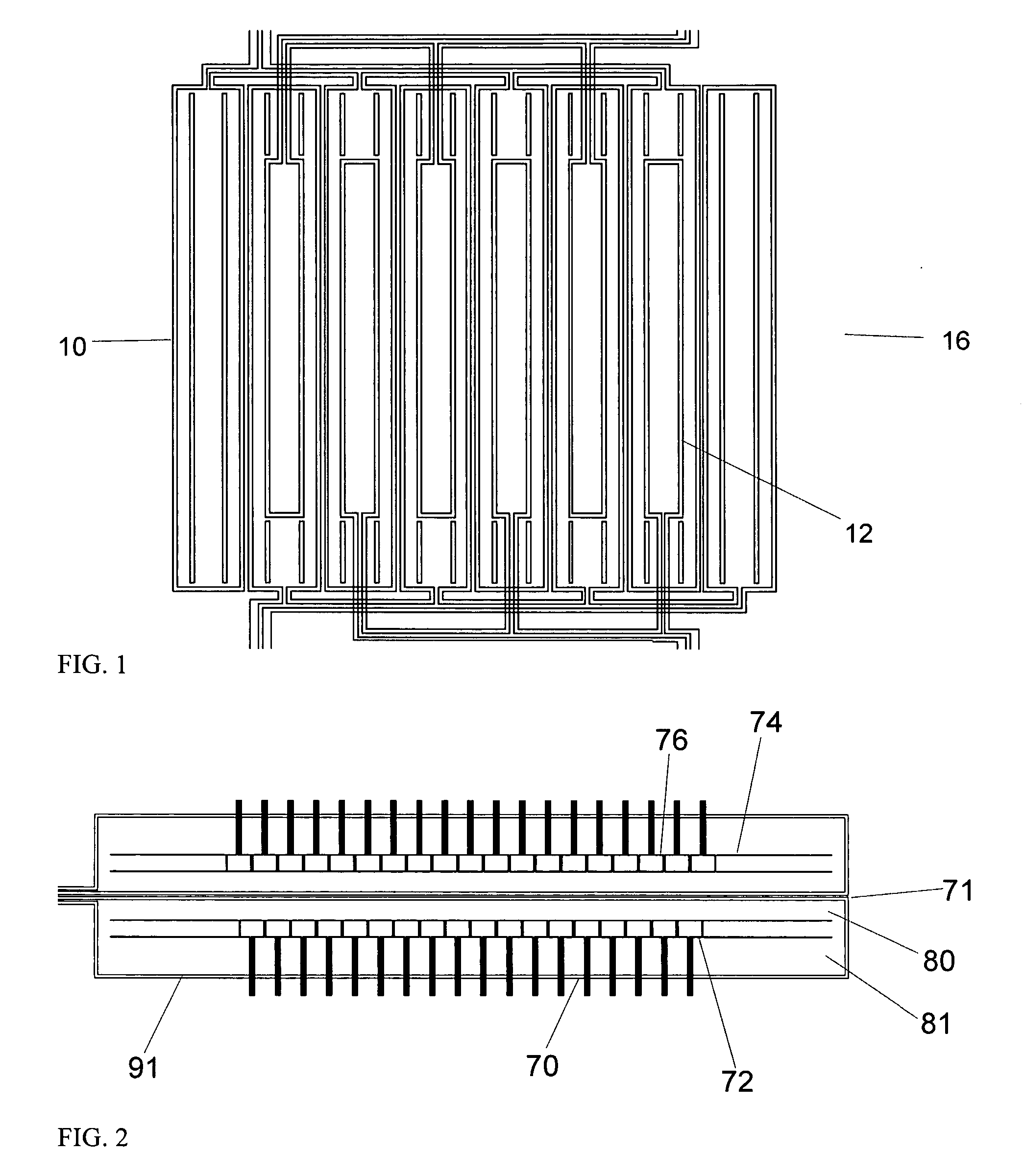
[0039] An example magnetic field sensor that operates in the magnetoquasistatic regime is shown in FIG. 1. This meandering winding magnetometer (MWM®) is a “planar,” conformable eddy-current sensor that was designed to support quantitative and autonomous data interpretation methods. The sensor 16 is described in U.S. Pat. Nos. 5,453,689, 5,793,206, 6,188,218, 6,657,429 and U.S. patent application Ser. No. 09 / 666,524 fil...


PUM

PropertyMeasurementUnit
frequenciesaaaaaaaaaa
crack lengthaaaaaaaaaa

Abstract

Nondestructive material condition monitoring and assessment is accomplished by placing, mounting, or scanning magnetic and electric field sensors and sensor arrays over material surfaces. The material condition can be inferred directly from material property estimates, such as the magnetic permeability, dielectric permittivity, electrical property, or thickness, or from a correlation with these properties. Hidden cracks in multiple layer structures in the presence of fasteners are detected by combining multiple frequency magnetic field measurements and comparing the result to characteristic signature responses. The threshold value for indicating a crack is adjusted based on a high frequency measurement that accounts for fastener type. The condition of engine disk slot is determined without removal of the disk from the engine by placing near the disk a fixture that contains a sensor for scanning through the slot and means for recording position within the slot. Inflatable support structures can be placed behind the sensor to improve and a guide can be used to align sensor with the slot and for rotating the disk. The condition of an interface between a conducting substrate and a coating is assessed by placing a magnetic field sensor on the opposite side of the substrate from the coating and monitoring at least one model parameter for the material system, with the model parameter correlated to the interfacial condition. The model parameter is typically a magnetic permeability that reflects the residual stress at the interface. Sensors embedded between material layers are protected from damage by placing shims on the faying surface. After determining the areas to be monitored and the areas likely to cause sensor damage, a shim thickness is determined and is then placed in at least one area not being monitored by a sensor. The condition of a test fluid is assessed through a dielectric sensor containing a contaminant-sensitive material layer. The properties of the layer are monitored with the dielectric sensor and correlated to contaminant level.

Description

RELATED APPLICATION [0001] This application claims the benefit of U.S. Provisional Application No. 60 / 610,817 filed Sep. 17, 2004, the entire teachings of which are incorporated herein by reference.GOVERNMENT SUPPORT [0002] The invention was supported, in whole or in part, by Contract Number DTFA03-01-C-00024 from the FAA and by Contract Number N68335-03-C-0123 from the Department of the Air Force. The Government has certain rights in the invention.BACKGROUND OF THE INVENTION [0003] The technical field of this invention is that of nondestructive materials characterization, particularly quantitative, model-based characterization of surface, near-surface, and bulk material condition for flat and curved parts or components. Characterization of bulk material condition includes (1) measurement of changes in material state, i.e., degradation / damage caused by fatigue damage, creep damage, thermal exposure, or plastic deformation; (2) assessment of residual stresses and applied loads; and (...

Claims


Application Information

Patent Timeline
Patent Type & Authority Applications(United States)
IPC IPC(8): G01N27/82
CPCG01N27/72
Inventor GOLDFINE, NEIL J.WINDOLOSKI, MARK D.GRUNDY, DAVID C.SHEIRETOV, YANKO K.SCHLICKER, DARRELL E.WASHABAUGH, ANDREW P.
Owner JENTEK SENSORS
Why Eureka
Try Eureka