Electrical rotating machine

a rotating machine and electric technology, applied in the direction of rotating parts of the magnetic circuit, magnetic circuit shape/form/construction, windings, etc., can solve the problems of increasing flux, difficulty in winding a coil around the middle magnetic pole, increasing copper loss in adjacent coils, etc., to achieve the effect of reducing copper loss with the total linkage flux maintained or increased

Inactive Publication Date: 2008-09-04
KOKUSAN DENKI CO LTD
View PDF4 Cites 13 Cited by
  • Summary
  • Abstract
  • Description
  • Claims
  • Application Information

AI Technical Summary

Benefits of technology

[0012]Preferably, three in-phase coils are arranged consecutively. Further, in the electrical rotating machine with permanent magnets, when the axis of the middle coil coincides in position with the magnetic pole of a permanent magnet opposite it, the axes of the two coils adjacent to the middle coil may deviate in position by an electrical angle of 20° from the magnetic poles of permanen

Problems solved by technology

However, because each magnetic pole is arranged to be opposite a permanent magnet at the same electrical angle, mechanical angles between the magnetic poles of the stator are not equal, but of three in-phase magnetic poles consecutively arranged, the left and right magnetic poles are displaced closer to the middle one, and hence

Method used


Image

  • Electrical rotating machine
  • Electrical rotating machine
  • Electrical rotating machine

Examples


embodiment

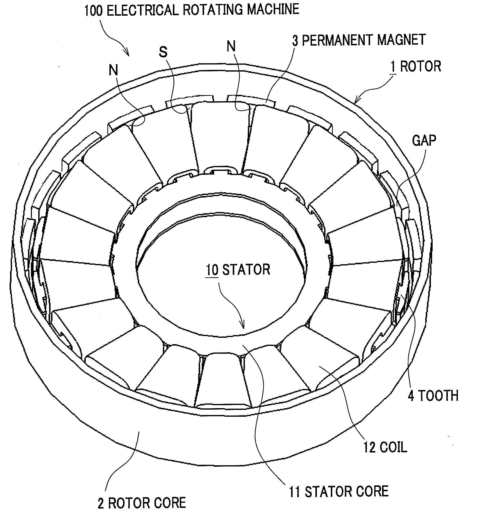
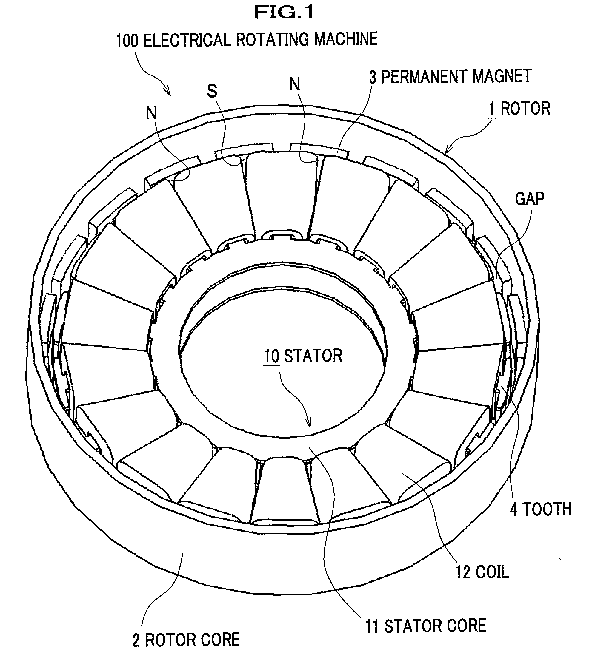
[0024]Will be described an electrical rotating machine according to an embodiment of the present invention with reference to FIG. 1.

[0025]In FIG. 1, an electrical rotating machine 100 is of an outer rotor type with permanent magnets and comprises a rotor 1 having multiple permanent magnets 3 fixed to the inner surface of a rotor core 2 and a stator 10 having multiple coils 12 wound through slots formed in a stator core 11 and has iron plates different in thickness (not shown) disposed at the opposite sides in its axis direction. The stator 10 is inserted in the rotor 1 with a slight gap between the stator 10 and the inner surface of the rotor 1, and the rotor 1 is rotatably supported by a bearing (not shown) to function as a fly wheel as well.

[0026]In the rotor 1, twenty plate-shaped permanent magnets 3 are arranged on the inner surface of the rotor core 2 at equal intervals in a circumferential direction such that N-poles alternate with S-poles. The rotor core 2 is in the shape of ...


PUM


Abstract

An electrical rotating machine with permanent magnets which is configured such that the ratio of the number of magnetic poles of permanent magnets 3 to the number of magnetic poles of coils 12 is at 10:9 or 8:9. The coils 12 are configured such that a middle coil U− and two adjacent coils U+, U+ on both sides thereof are in-phase connected to be in-phase coils for each phase, and there is satisfied the relationship that T2>T1 and T2>T3, where T2 is the turn number of the middle coil U−, and T1 and T3 are the turn numbers of the adjacent coils U+, U+.

Description

CROSS REFERENCE TO RELATED APPLICATIONS[0001]This application claims the foreign priority benefit under Title 35, United States Code, §119(a)-(d) of Japanese Patent Application No. 2007-046449, filed on Feb. 27, 2007 in the Japan Patent Office, the disclosure of which is herein incorporated by reference in its entirety.BACKGROUND OF THE INVENTION[0002]1. Field of the Invention[0003]The present invention relates to an electrical rotating machine using permanent magnets and coils.[0004]2. Description of the Related Art[0005]Electrical rotating machines such as generators have a stator comprising a plurality of coils and a rotor comprising a plurality of permanent magnets and are configured such that rotational magnetic fields generated by the rotating permanent magnets crossing the coils, thereby generating electromotive force across the coils.[0006]For example, in International Publication WO / 03 / 098781 pamphlet discloses a magnet field rotation type of electrical rotating machine wit...

Claims


Application Information

Patent Timeline
IPC IPC(8): H02K3/28H02K1/16H02K1/27H02K3/12
CPCH02K21/22
Inventor KOKA, HIDETOSHIKANAZAWA, HIROSHITERUMOTO, SUSUMUNAKAGAWA, MASANORI
Owner KOKUSAN DENKI CO LTD
Why Eureka
Try Eureka