Methods of predicting cavitation damage

a technology of cavitation damage and cavitation technique, applied in the field of cavitation damage, can solve problems such as material failure, equipment downtime, and cavitation damag

Active Publication Date: 2008-09-04
CATERPILLAR INC
View PDF10 Cites 14 Cited by
  • Summary
  • Abstract
  • Description
  • Claims
  • Application Information

AI Technical Summary

Problems solved by technology

This is known to those of ordinary skill in the art as cavitation damage.
Cavitation damage can be extremely problematic to the performance of hydrodynamic components and, in some instances, may lead to material failure.
In addition, cavitation damage can often result in equipment downtime, as well as warranty exposure and negative commercial effects for the equipment's manufacturer.
Design solutions were not tested over multiple variables, and further, many hundred man-hours of resources were expended.
Even when experiments were designed to include multiple variables, cavitation damage still remained unpredictable and, consequently, difficult to analyze.
This inability to accurately predict a...

Method used


Image

  • Methods of predicting cavitation damage
  • Methods of predicting cavitation damage
  • Methods of predicting cavitation damage

Examples


Embodiment Construction

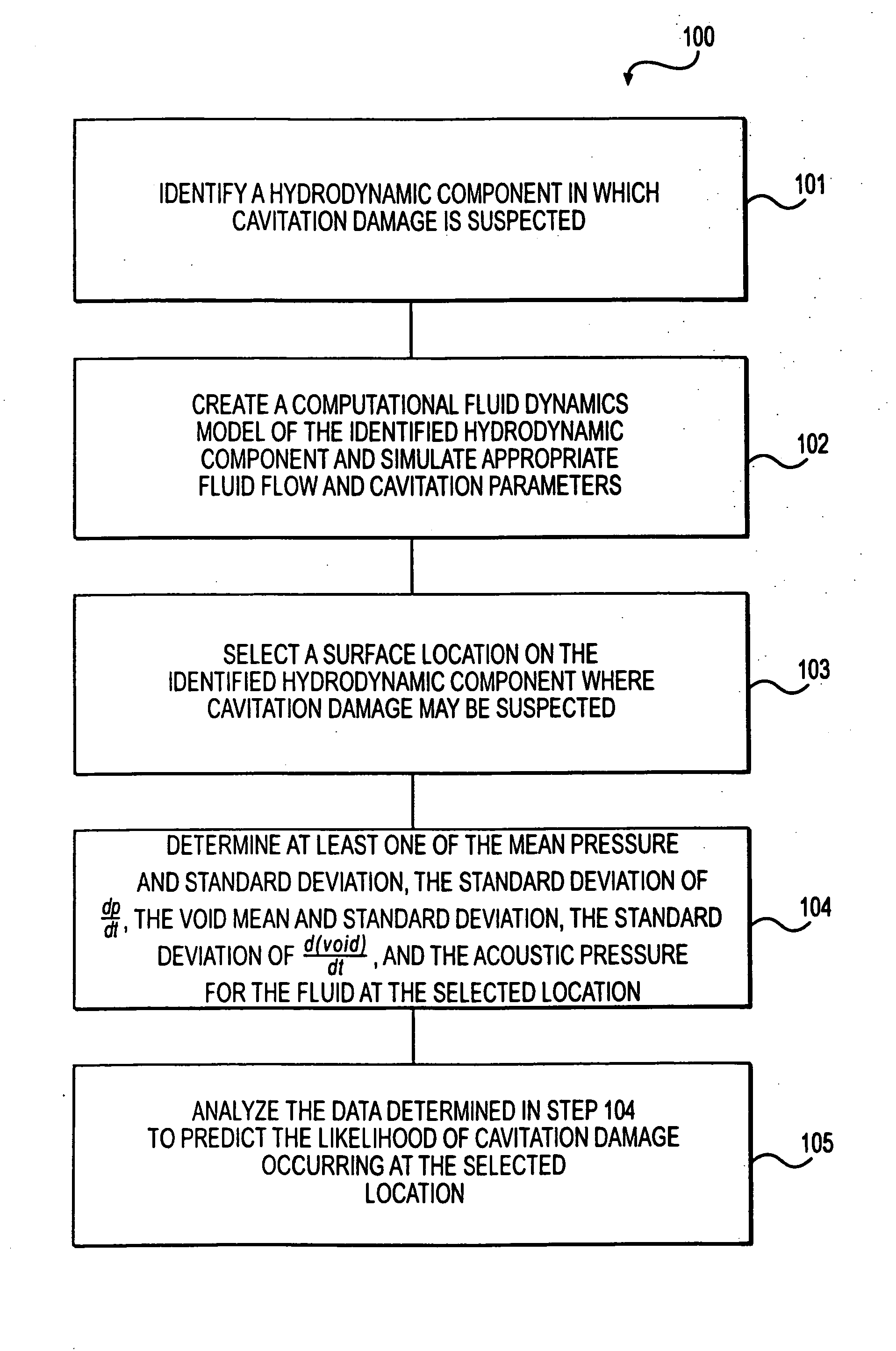
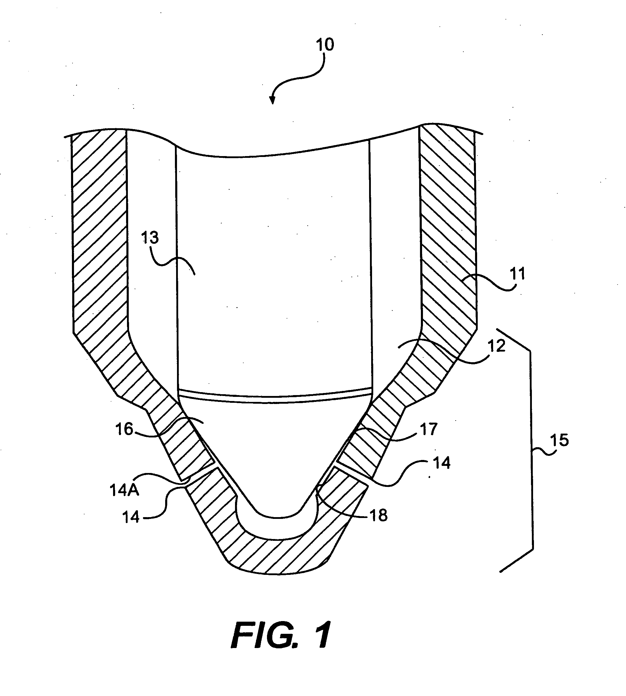
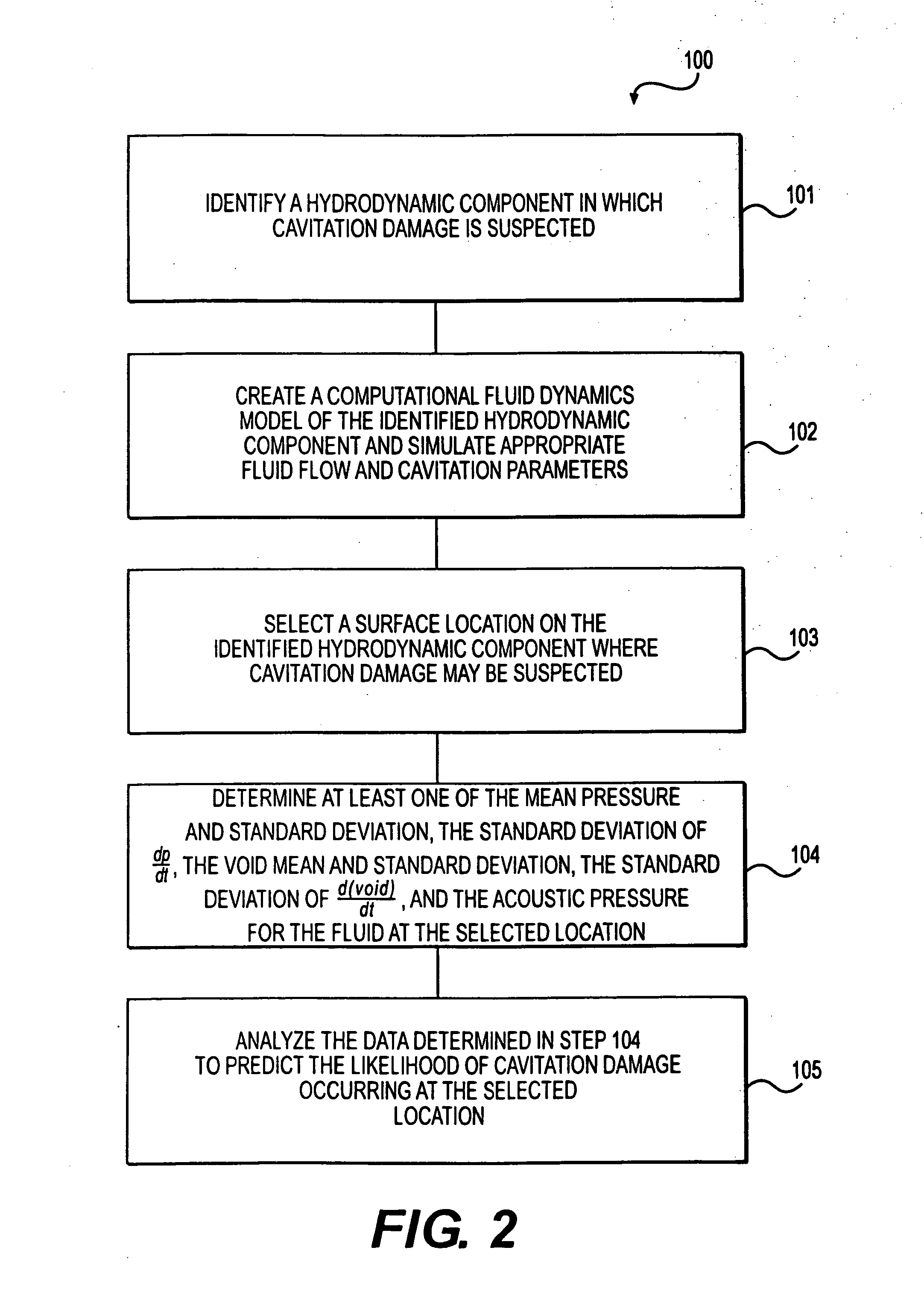
[0016]For discussion purposes only, the principles of the present disclosure, including method 100 discussed below, are described in connection with the exemplary hydrodynamic component depicted in FIG. 1. Although the hydrodynamic component depicted in FIG. 1 is represented as a fuel injector nozzle 10, those having ordinary skill in the art will recognize that the principles of the present disclosure may be applied to any type of hydrodynamic component, including, but not limited to, pumps, turbines, valves, propellers, pipes for transporting fluids (e.g., liquids), and any other component exposed to a proximally flowing fluid. In addition, it will also be readily apparent to those having ordinary skill in the art that the principles of the present disclosure may be utilized with components experiencing cavitation in the absence of actual flowing fluid.

[0017]In the illustrated exemplary embodiment, fuel injector nozzle 10 may include an injector body 11 that defines a hollow inter...


PUM


Abstract

A method is provided for predicting the likelihood of cavitation damage occurring on a surface of a hydrodynamic component. The method may include creating a computational fluid dynamics (CFD) simulation of the hydrodynamic component, wherein creating the CFD simulation includes simulating a fluid proximal to the surface of the hydrodynamic component. The method may also include selecting a location on the surface of the hydrodynamic component, wherein the selected location is exposed to the simulated fluid. The method may further include determining the mean pressure and standard deviation, the standard deviation of the rate of change in pressure, the mean void percentage and standard deviation, and the standard deviation of the rate of change in void percentage for the fluid at the selected surface location. The method may also include analyzing at least one of the mean pressure and standard deviation, the standard deviation of the rate of change in pressure, the mean void percentage and standard deviation, and the standard deviation of the rate of change in void percentage for the fluid at the selected surface location to predict the likelihood of cavitation damage occurring at the selected surface location.

Description

PRIORITY[0001]This application claims the benefits of priority to U.S. Provisional Patent Application No. 60 / 877,633, entitled METHODS OF PREDICTING CAVITATION DAMAGE, filed on Dec. 29, 2006, the entirety of which is incorporated herein by reference.TECHNICAL FIELD[0002]The present disclosure relates generally to cavitation damage and, more particularly, to methods of predicting the likelihood of cavitation damage occurring in hydrodynamic components having surfaces exposed to a fluid.BACKGROUND[0003]Pressurized fluid systems, such as, for example, fuel injectors and pumps, are frequently susceptible to the phenomenon known as “cavitation.” As known to those having ordinary skill in the art, cavitation generally refers to the formation of vapor bubbles within a fluid stream when, for example, the fluid's operational pressure drops below the fluid's vapor pressure. For example, cavitation can occur in flowing liquid when the speed or velocity of the liquid increases such that the pre...

Claims


Application Information

Patent Timeline
IPC IPC(8): G06F19/00
CPCG06F2217/16G06F17/5018G06F30/23G06F2111/10
Inventor STOCKNER, ALAN R.IBRAHIM, DANIEL RICHARDGAVAISES, MANOLISTHEODORAKAKOS, ANDREAS
Owner CATERPILLAR INC
Why Eureka
Try Eureka