
Re-Design of Operating Room Tables

a technology for operating room tables and tables, applied in the field of surgical tables, can solve the problems of insufficient capacity for rotation, tilting and other translational movements to provide the necessary surgical access, disadvantage of providing numerous operating room tables, and limited operating room floor space, so as to achieve greater tilting and cantilevering capabilities, a larger table top extension, and a larger patient population.

Inactive Publication Date: 2008-09-11
OPTIMUS SERVICES
View PDF5 Cites 45 Cited by
  • Summary
  • Abstract
  • Description
  • Claims
  • Application Information

AI Technical Summary

Benefits of technology

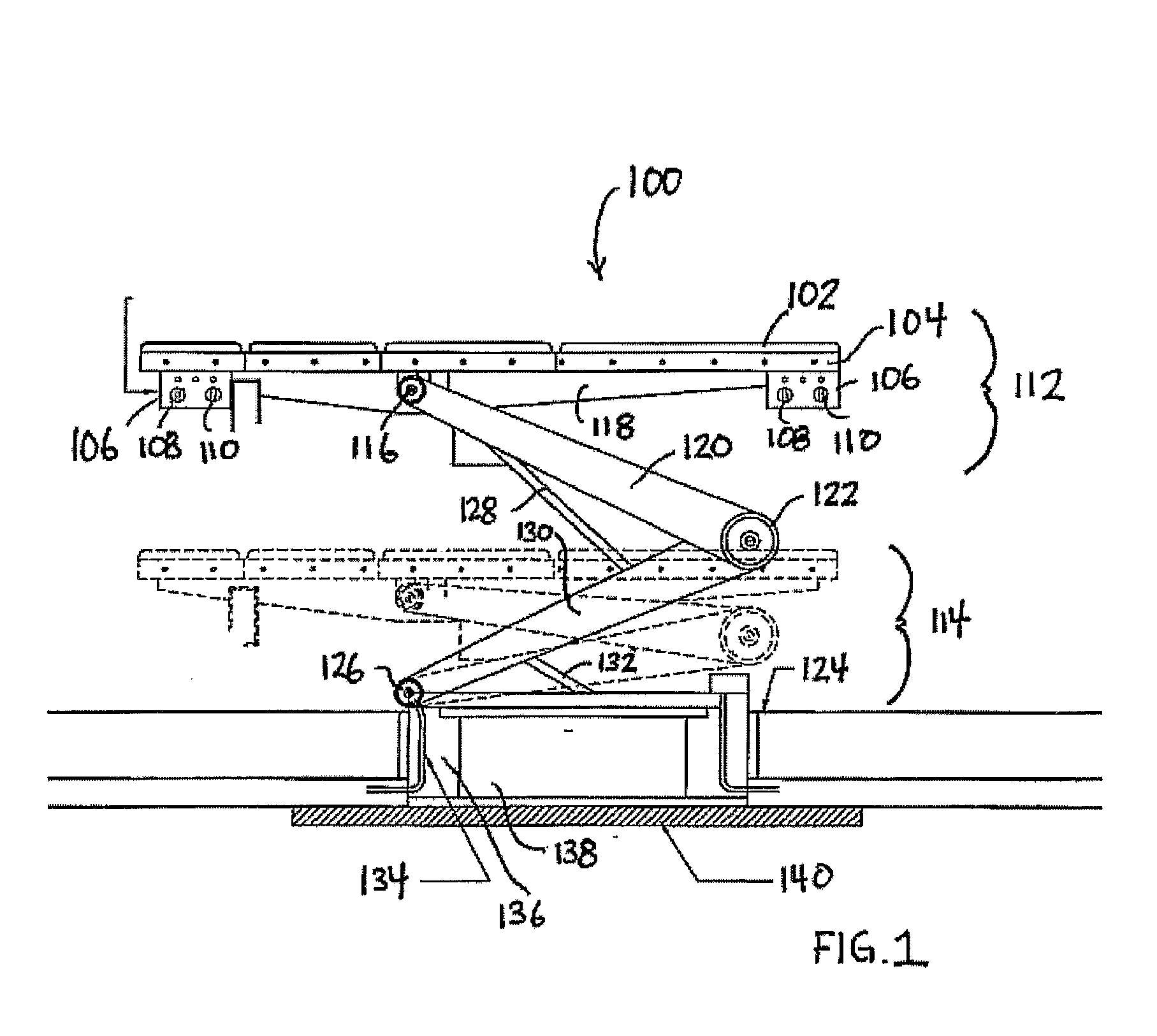
[0022]A patient table, modified with a fixed-base design thereby allowing for heavier patients, greater tilting and cantilevering capabilities, greater table top extension (i.e. providing head to toe coverage), and overall stability, is described. The operating room table re-design includes incorporation of utility sources into the architecture of the table, so that utilities, such as wiring, vacuum, and gas hoses, arise from the table itself, rather than tracking over the operating room floor. The source of all utilities to the table (as opposed to those emanating from the table) may come from an underground connection. Further, the table is interchangeable with tables customized for a specific procedure.
[0024]As operating room procedures change, the table may be interchanged with an alternative table provided it is adapted to dock with the support structure and support structure utilities. The table is further adapted to provide utility connections at various points along the table, thereby allowing easy, unobstructed access to critical utilities.
[0025]In keeping with the present invention, it is an object of the invention to provide an operating room table and support column that allows the patient support means to be separated from the support column, and to be replaced with an alternative patient support means adapted for the surgical procedure at hand.

Problems solved by technology

The capability of rotation, tilting, and other translational movements is insufficient to provide the necessary surgical access in all cases.
As a result, modem operating rooms utilize numerous surgical tables; however, operating room floor space is typically scarce.
As a result, it is a disadvantage to provide numerous operating room tables, each configured for a particular type of procedure.
Because manual positioning is time-consuming, it is dangerous, as a medical procedure emergency may require quick access to a particular site.
Another deficiency in modern surgical tables is the lack of convenient access to utilities required for a surgical procedure.
Of the many utilities required comes the related safety issue that the presence of these numerous cables, hoses, and wires causes.
A surgeon or attendant who trips on a cable can cause injury to the surgeon and to the patient.
Further, a table, which allows positioning to provide access to a patient, is severely limited to further adjustment during a procedure as cables, wires, and hoses impose limits on the ability of a surgeon to reposition a patient.

Method used


Image

  • Re-Design of Operating Room Tables
  • Re-Design of Operating Room Tables
  • Re-Design of Operating Room Tables

Examples


Embodiment Construction

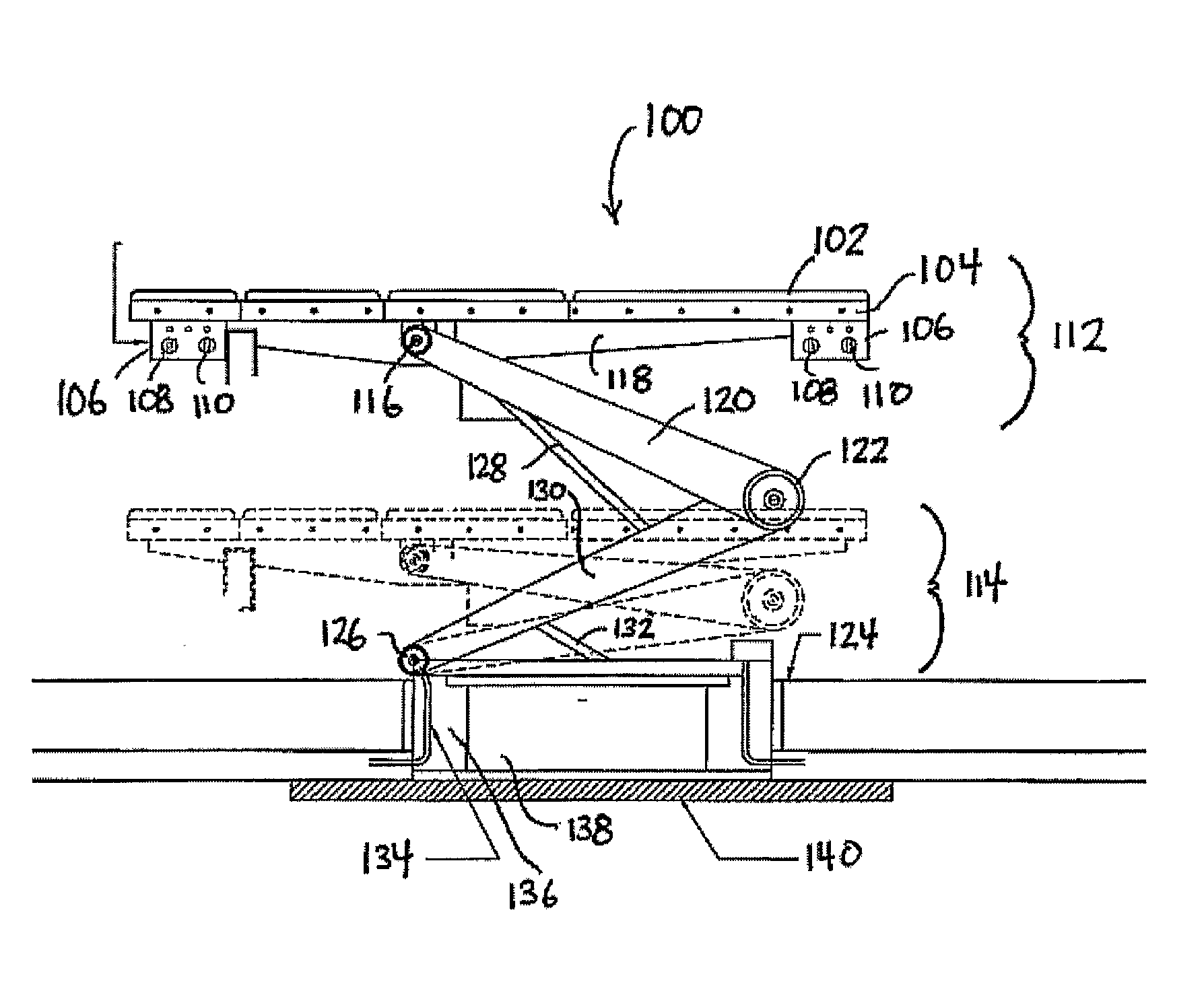
[0036]FIG. 1 is a side view of surgical table 100 in raised 112 position or in lowered position 114 above floor 124 of the operating room. Housing 136 is provided for surgical table 100. Surgical bed 102 is solidly attached to a strong sub-base, such as, for example, steel plate 140, which is bolted or otherwise attached into the sub floor (below 124), made from, for example, concrete. Powered braces 128 and 132 are used to raise and lower top frame 104 with pads 102 via arms 120 and 130 riding in pivots 116, 122, and 126. Robustly built to support heavy patients, such as, for example, a 550-pound patient, table 100 has upper support rib 118; and the tabletop of table 100 can cantilever, rotate, and slide. All utilities, such as power, vacuum, electrical, and gas, are fed through the housing 136 as illustrated by lines 134. These lines are carried to outlet / inlet 106 at either head or toe ends. If necessary, utility outlet / inlets 106 have utility connections 108 and 110 and are acce...


PUM


Abstract

A patient table, modified with a fixed-base design thereby allowing for heavy patients, providing tilting and cantilevering capabilities, table top extension (i.e. providing head to toe coverage), and overall stability, is described. The operating room table re-design includes incorporation of utility sources into the architecture of the table, so that utilities, such as wiring, vacuum, and gas hoses, arise from the table itself. The source of all utilities to the table (as opposed to those emanating from the table) may come from an underground connection. Further, the table is interchangeable with tables customized for a specific procedure.

Description

CROSS-REFERENCE TO RELATED APPLICATIONS[0001]This application claims the benefit of provisional patent application U.S. Ser. No. 60 / 701,106, filed Jul. 20, 2005 by the present inventor. The contents of U.S. Ser. No. 60 / 701,106 are expressly incorporated herein by reference thereto.[0002]The following references are hereby explicitly incorporated by reference thereto:[0003]U.S. Pat. No. 4,101,120[0004]U.S. Pat. No. 5,048,071[0005]U.S. Pat. No. 5,231,719[0006]U.S. Pat. No. 6,170,102[0007]Applications filed along with present application by current inventor on this date entitled:[0008]IN-CEILING FOCUS LOCATED SURGICAL LIGHTING[0009]HOSPITAL OPERATING ROOM RE-DESIGN[0010]AMBIENT LIGHTING IN HOSPITAL SURGICAL ENVIRONMENTS[0011]USE OF ULTRAVIOLET GERMICIDAL IRRADIATION IN HEALTH CARE ENVIRONMENTS[0012]IN-WALL WASTE RECEPTACLES FOR HOSPITAL AND LABORATORY ENVIRONMENTS[0013]ROBOTIC FLOOR CLEANING WITH STERILE, DISPOSABLE CARTRIDGES[0014]MULTIFUNCTIONAL FLOOR PODSBACKGROUND OF THE INVENTION ...

Claims


Application Information

Patent Timeline
IPC IPC(8): A61G13/06
CPCA47L11/302A47L11/40A47L2201/00A61B19/0287A61B19/0288A61B2019/0202H01R27/02A61B2019/0267B01L1/50B65F1/0093B65F1/06E04B5/48H01R13/005A61B2019/025A61G13/02A61G13/06A61G13/107A61B50/13A61B50/36A61B50/362A61B2050/005A61B2050/314
Inventor MANGIARDI, JOHN R.
Owner OPTIMUS SERVICES
Learn More