Electrical switching apparatus, and conductor assembly and shunt assembly therefor

a technology of electrical switching apparatus and conductor assembly, which is applied in the direction of circuit-breaking switches, contact mechanisms, dynamo-electric relays, etc., can solve the problems of less than desired blow-on and achieve the effect of improving the withstand performance of circuit breaker

Active Publication Date: 2008-09-11
EATON INTELLIGENT POWER LTD
View PDF25 Cites 13 Cited by
  • Summary
  • Abstract
  • Description
  • Claims
  • Application Information

AI Technical Summary

Benefits of technology

[0010]These needs and others are met by embodiments of the invention, which are directed to a conductor assembly for an electrical switching apparatus such as, for example, a low-voltage circuit breaker, and a shunt assembly therefor, which optimizes the forces on the movable arms of the conductor assembly and thereby improves the withstand performance of the circuit breaker.

Problems solved by technology

However, the magnetic repulsion force is, in general, not translated into torque of the fingers of the movable contact assembly as efficiently and effectively as possible, resulting in blow-on performance of the circuit breaker that is less than desired.

Method used


Image

  • Electrical switching apparatus, and conductor assembly and shunt assembly therefor
  • Electrical switching apparatus, and conductor assembly and shunt assembly therefor
  • Electrical switching apparatus, and conductor assembly and shunt assembly therefor

Examples


Embodiment Construction

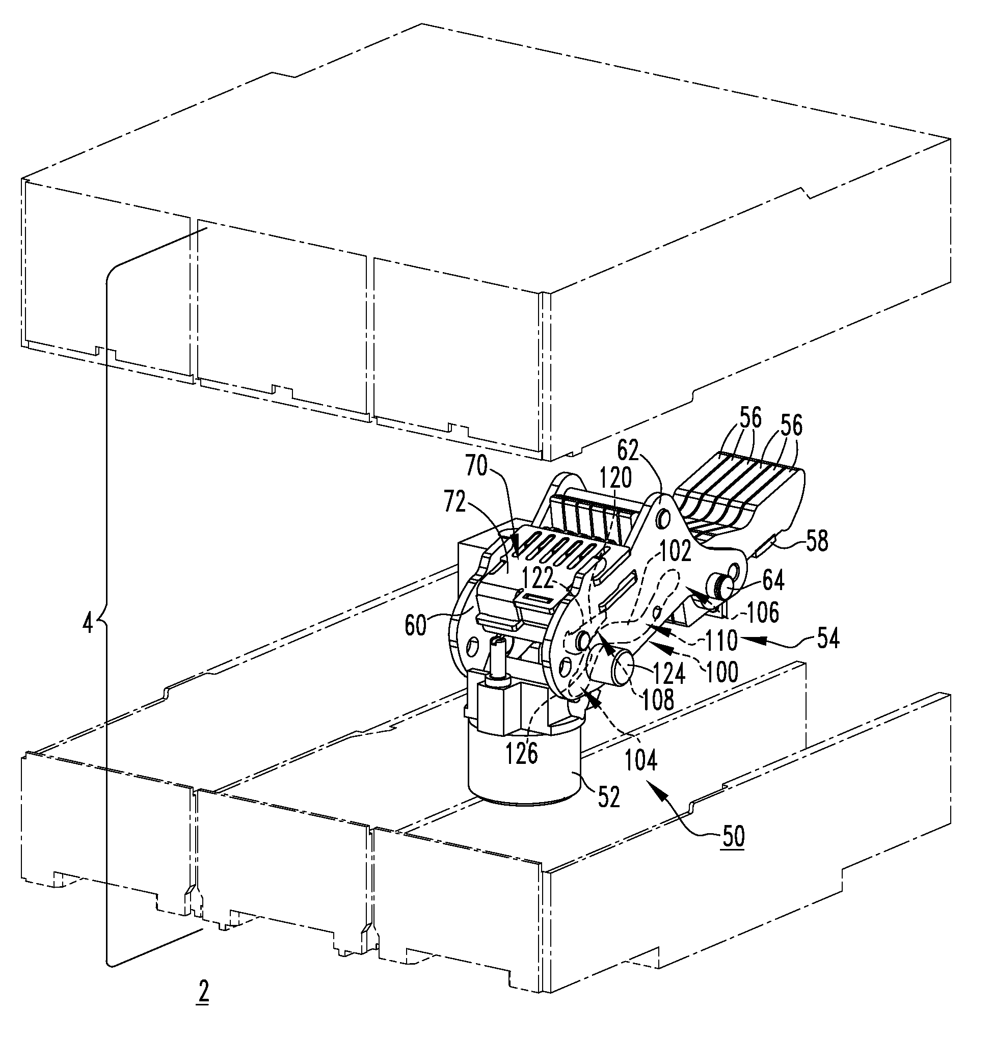
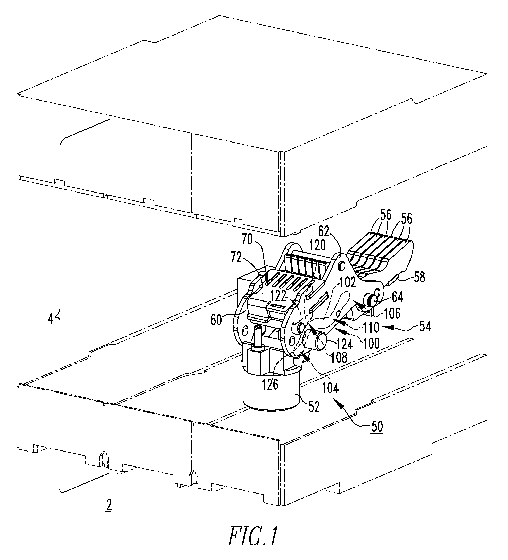
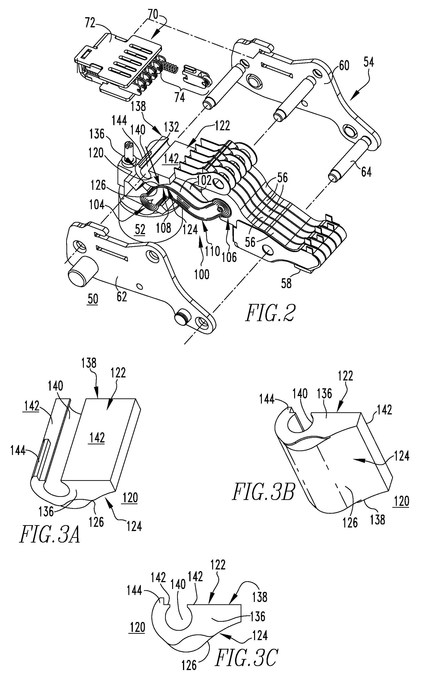
[0024]For purposes of illustration, embodiments of the invention will be described as applied to a device for efficiently translating the magnetic repulsion force in generally S-shaped shunts for low-voltage circuit breaker conductor assemblies into torque of the movable contact arms of the movable contact assembly of the breaker, although it will become apparent that they could also be applied to translate such force in flexible conductive elements which are arranged in any suitable number and / or configuration for use in a wide variety of electrical switching apparatus (e.g., without limitation, circuit switching devices and other circuit interrupters, such as contactors, motor starters, motor controllers and other load controllers) other than low-voltage circuit breakers.

[0025]Directional phrases used herein, such as, for example, left, right, top, bottom, upper, lower, front, back, clockwise, counterclockwise and derivatives thereof, relate to the orientation of the elements show...


PUM


Abstract

A shunt assembly is provided for an electrical switching apparatus including a conductor assembly having a load conductor and a movable contact assembly with a number of movable contact arms. The movable contact assembly is movable in response to a fault current. The shunt assembly includes a number of flexible conductive elements each having a first end electrically connected to the load conductor, a second end electrically connected to a corresponding one of the movable contact arms, and a number of bends disposed between the first and second ends. At least one constraint element is disposed proximate a corresponding one of the bends and constrains movement of the flexible conductive element in response to the fault current, thereby translating the magnetic repulsion force associated with the fault current into a corresponding torque of the movable contact arms of the movable contact assembly.

Description

CROSS REFERENCE TO RELATED APPLICATION[0001]This Application is related to commonly assigned, copending application Ser. No. 11 / 549,277, filed Oct. 13, 2006, entitled “Electrical Switching Apparatus, and Conductor Assembly and Independent Flexible Conductive Elements Therefor,” which is hereby incorporated herein by reference.BACKGROUND OF THE INVENTION[0002]1. Field of the Invention[0003]The invention relates generally to electrical switching apparatus and, more particularly, to conductor assemblies for electrical switching apparatus, such as circuit breakers. The invention also relates to shunt assemblies for circuit breaker conductor assemblies.[0004]2. Background Information[0005]Electrical switching apparatus, such as circuit breakers, provide protection for electrical systems from electrical fault conditions such as, for example, current overloads, short circuits, abnormal voltage and other fault conditions. Typically, circuit breakers include an operating mechanism which open...

Claims


Application Information

Patent Timeline
Patent Type & Authority Applications(United States)
IPC IPC(8): H01H83/00
CPCH01H1/226H01H1/5822H01H77/107
Inventor WEISTER, NATHAN J.RAKUS, PAUL R.SHEA, JOHN J.POLLITT, WILLIAM C.
Owner EATON INTELLIGENT POWER LTD
Why Eureka
Try Eureka