Red Eye False Positive Filtering Using Face Location and Orientation

a false positive and face location technology, applied in the field of red eye false positive filtering using face location and orientation, can solve the problems of high computation and memory resource requirements of face detection-based automatic redeye reduction techniques, visual displeasing images, and inability to detect faces that are rotated in-plane or out-of-plane with respect to the image plan

Active Publication Date: 2008-09-11
FOTONATION LTD
View PDF99 Cites 60 Cited by
  • Summary
  • Abstract
  • Description
  • Claims
  • Application Information

AI Technical Summary

Benefits of technology

[0007]A method of detecting and correcting a red-eye defect within a digital image is provided. An image is acquired having one or more non red eye defect regions which are red in color. A first stage initial segmentation of candidate redeye regions is performed to determine a first set of one or more confirmed redeye regions designated for correction. A location and orientation of any faces within the image are determined. The first set of confirmed redeye regions is analyzed based on the determined location and orientation of faces to determine a probability that each confirmed redeye region appears at a position of an eye. Any confirmed redeye regions having at least a certain threshold probability of being a false positive are removed from the first set, and a second set is generated. The second set of confirmed red eye regions is corrected and a red eye corrected image is generated which has the second set of confirmed red eye regions corrected therein. The redeye corrected image is electronically stored, transmitted, further processed or edited, or displayed, or combinations thereof.
[0008]The performing of the first stage initial segmentation of red eye regions may include pixel analyzing. The performing of the first stage initial segmentation of red eye regions may include falsing and verification filtering. The analyzing and removing may be performed prior to any correcting of the image. The first set of confirmed redeye regions may be initially corrected, and an initial corrected image may be generated prior to the analyzing and removing and the generating of the red eye corrected image. One or more detected faces may include at least one red eye defect such that the second set comprises a non-empty set, or the second set may be empty such that no actual redeye regions are corrected in the image.
[0009]An embedded image acquisition and processing system includes an image acquisition subsystem. A red eye filter performs in a first stage an initial segmentation of candidate redeye regions detected within an acquired image to determine a first set of one or more confirmed redeye regions designated for correction. A face location and orientation detector and an analysis filter determine a probability that each confirmed redeye region appears at a position of an eye based on determining face location and orientation information. A processor corrects any red eye defects of the confirmed red eye regions of the first set minus any having at least a certain threshold probability of being a false positive and generates a red eye corrected image. The red eye corrected image is electronically stored, transmitted, further processed or edited, or displayed, or combinations thereof. No redeye defects are corrected when no faces are detected within the image.
[0010]One or more storage devices having processor-readable code embodied therein are also provided for programming one or more processors to perform any of the methods described herein alone or in combination with techniques described in references incorporated herein.

Problems solved by technology

In general, face-detection-based automatic redeye reduction techniques have high computation and memory resource requirements.
In addition, most of the face detection algorithms are only able to detect faces that are oriented in an upright frontal view; these approaches cannot detect faces that are rotated in-plane or out-of-plane with respect to the image plane.
Although somewhat rare, applying red eye correction to them can result in a visually displeasing image.

Method used


Image

  • Red Eye False Positive Filtering Using Face Location and Orientation
  • Red Eye False Positive Filtering Using Face Location and Orientation
  • Red Eye False Positive Filtering Using Face Location and Orientation

Examples


Embodiment Construction

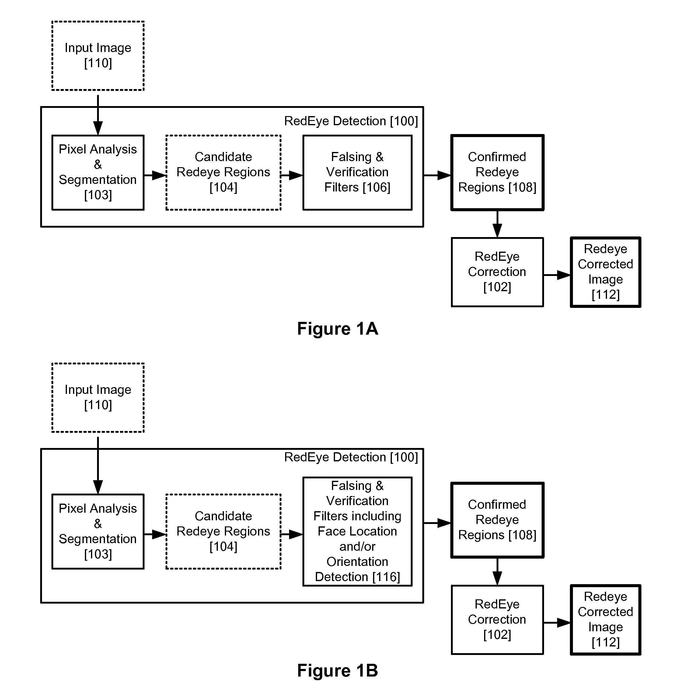
[0020]A redeye filter process is illustrated in FIG. 1A. An input image is first analyzed by a redeye detection stage 100 at a pixel level 103 and segmented into candidate redeye regions 104. A further series of falsing and verification filters 106 are then applied to the candidate regions and a set of confirmed redeye regions 108 is thereby determined. A correction filter (pixel modifier) 102 is next applied to the confirmed regions and a final image 112, corrected for redeye, is generated.

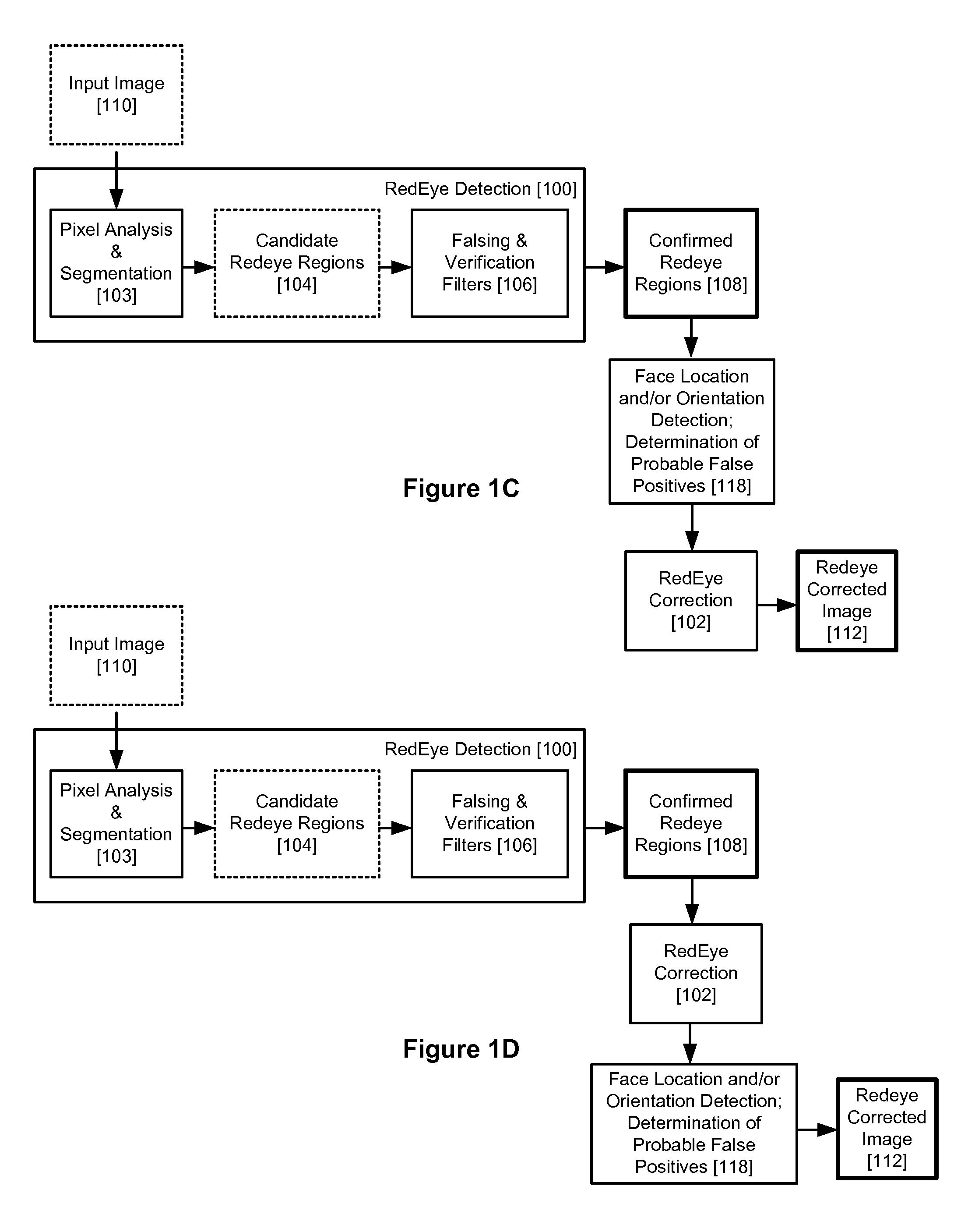
[0021]In embodiments herein, a face detection algorithm is applied either as a component of an advantageous falsing and verification filter 106, or after the set of confirmed red eye regions is initially determined at 108. This face detection algorithm determines location and / or orientation of the face. This provides information as to where specifically that any eyes probably exist and / or where specifically that eyes probably do not exist within the image.

[0022]FIG. 1B illustrates a process inclu...


PUM


Abstract

An image is acquired including a red eye defect and non red eye defect regions having a red color. An initial segmentation of candidate redeye regions is performed. A location and orientation of one or more faces within the image are determined. The candidate redeye regions are analyzed based on the determined location and orientation of the one or more faces to determine a probability that each redeye region appears at a position of an eye. Any confirmed redeye regions having at least a certain threshold probability of being a false positive are removed as candidate redeye defect regions. The remaining redeye defect regions are corrected and a red eye corrected image is generated.

Description

PRIORITY[0001]This application claims the benefit of priority to U.S. provisional patent application No. 60 / 892,882, filed Mar. 5, 2007, which is incorporated by reference.BACKGROUND[0002]Redeye is the appearance of an unnatural reddish coloration of the pupils of a person appearing in an image captured by a camera with flash illumination. Redeye is caused by light from the flash reflecting off blood vessels in the person's retina and returning to the camera.[0003]A large number of image processing techniques have been proposed to detect and correct redeye in color images. In general, these techniques typically are semi-automatic or automatic. Semi-automatic redeye detection techniques rely on human input. For example, in some semi-automatic redeye reduction systems, a user manually identifies to the system the areas of an image containing redeye before the defects are corrected.[0004]Many automatic redeye reduction systems rely on a preliminary face detection step before redeye are...

Claims


Application Information

Patent Timeline
Patent Type & Authority Applications(United States)
IPC IPC(8): G06K9/00
CPCG06K9/00228G06T2207/30216G06T7/0083G06K9/00281G06T7/12G06V40/171G06V40/161G06F18/00
Inventor STEINBERG, ERANDRIMBAREAN, ALEXANDRUNANU, FLORIN
Owner FOTONATION LTD
Why Eureka
Try Eureka