
Tools for use with moving organs

a technology for moving organs and tools, applied in the field of medical devices, can solve the problems of difficult use in clinical decisions, difficult observation of images, and constant shift of images, and achieve the effect of reducing imaged motion

Inactive Publication Date: 2008-09-11
SYNC RX
View PDF106 Cites 108 Cited by
  • Summary
  • Abstract
  • Description
  • Claims
  • Application Information

AI Technical Summary

Benefits of technology

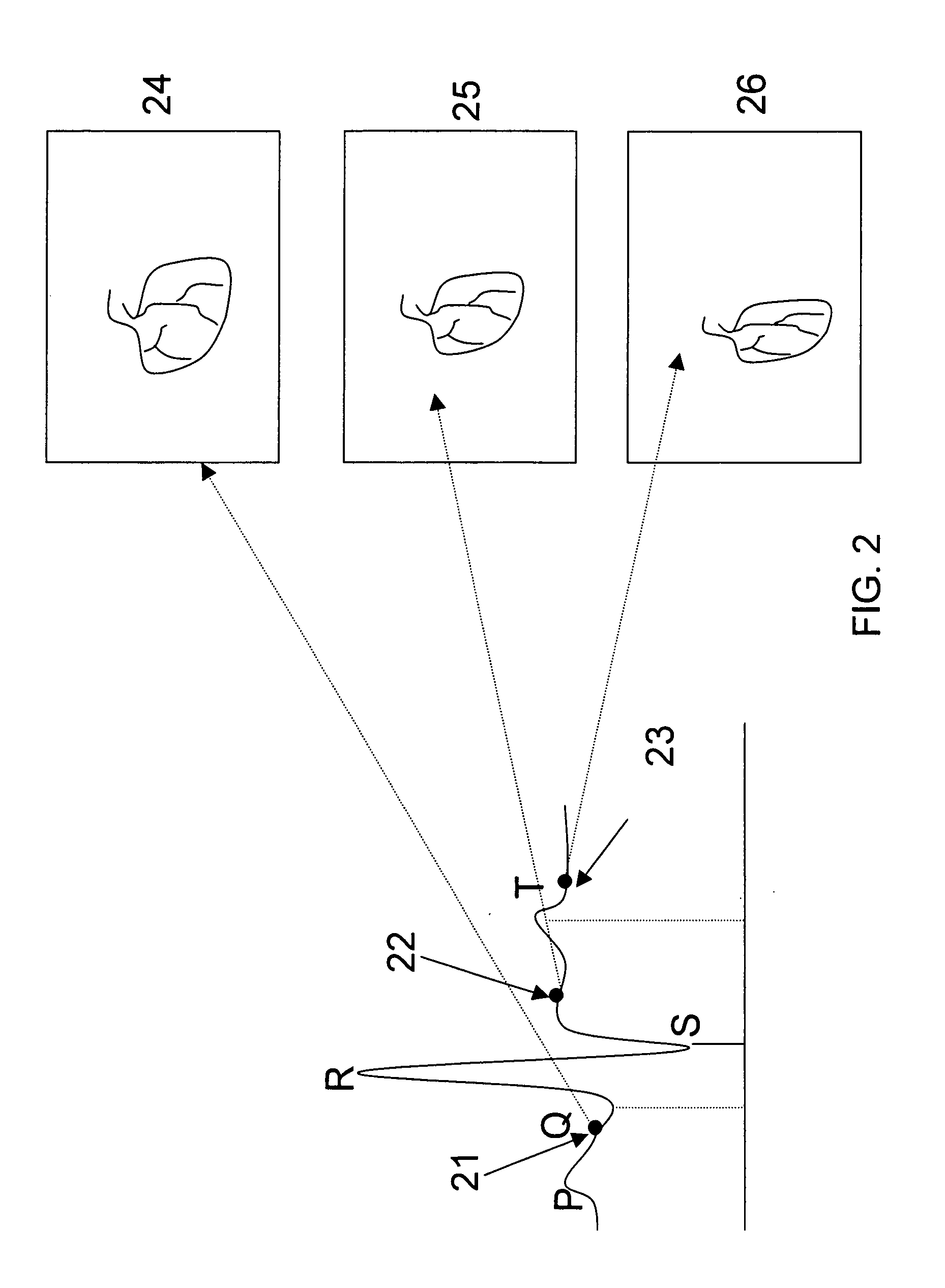
[0106]Consequently, the tool is typically actuated only during one or more selected same phases in a motion cycle of the organ. In some embodiments, the synchronized actuation of medical tools controls the application of linear motion, angular motion, energy, substance delivery, or any combination thereof.
[0417]In an embodiment, the control unit is configured to generate the stabilized set of image frames by image tracking at least some of the plurality of image frames to reduce imaged motion of the portion of the subject's body associated with the cyclic activity.

Problems solved by technology

Such images typically shift constantly and are also prone to blurring.
Consequently, such images are typically difficult to observe, and are difficult to use in making clinical decisions over an extended period of time (such as the entire duration of the procedure).
A difficulty associated with such procedures is the targeted deployment and / or actuation of tools with respect to the moving body part.

Method used


Image

  • Tools for use with moving organs
  • Tools for use with moving organs
  • Tools for use with moving organs

Examples


Embodiment Construction

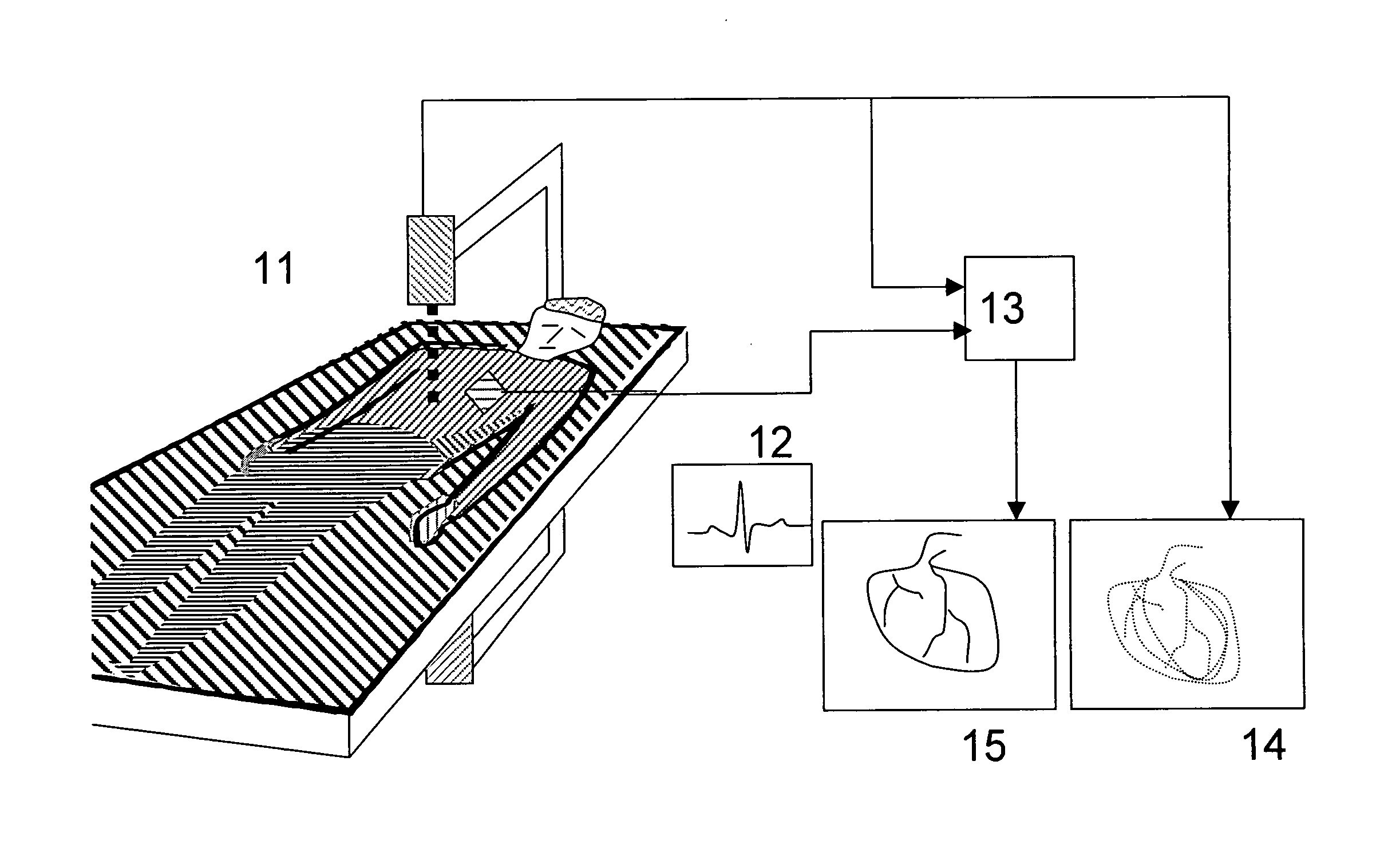
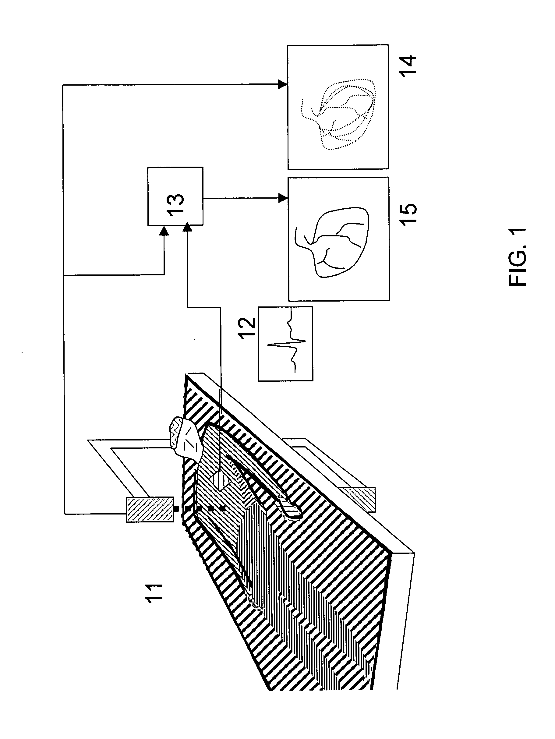
[0466]As used herein:[0467]The term “physiological signal or process” refers to any cyclical physiological signal or process in the patient's body including, but not limited to, ECG, blood pressure (e.g., systolic and diastolic), Peripheral Arterial Tone, EEG, respiration, the shifting / expansion / contraction of an organ, acquired images in which any of the above signals or processes may be observed, or any combination, derivation, extrapolation or manipulation thereof.[0468]The terms “medical tool,”“tool” and “probe” mean any type of a diagnostic or therapeutic or other functional tool including, but not limited to, a cardiovascular catheter, a stent delivery and / or placement and / or retrieval tool, a balloon delivery and / or placement and / or retrieval tool, a valve delivery and / or placement and / or retrieval tool, a graft delivery and / or placement and / or retrieval tool, a tool for the delivery and / or placement and / or retrieval of an implantable device or of parts of such device, an imp...


PUM


Abstract

A sensor senses a phase of cyclic activity of a portion of a subject's body. A control unit, in a first cycle of the cyclic activity, moves a portion of a tool, in a given direction, in response to the sensor sensing that the cyclic activity is at a first given phase thereof. The control unit, following the given phase and prior to an occurrence of the given phase in a subsequent cycle, inhibits the tool's movement. The control unit in a second cycle, subsequent to the inhibiting, moves the tool in the given direction, in response to the sensor sensing that the second cycle is at the given phase, without moving the tool in an opposite direction, between (a) moving the tool in the given direction in the first cycle, and (b) moving the tool in the given direction in the second cycle. Other embodiments are also described.

Description

CROSS-REFERENCES TO RELATED APPLICATIONS[0001]The present patent application claims the benefit of U.S. Provisional Patent Application Nos. 60 / 906,091 filed on Mar. 8, 2007, 60 / 924,609 filed on May 22, 2007, 60 / 929,165 filed on Jun. 15, 2007, 60 / 935,914 filed on Sep. 6, 2007, and 60 / 996,746 filed on Dec. 4, 2007, all named “Apparatuses and methods for performing medical procedures on cyclically-moving body organs,” all of which applications are incorporated herein by reference.[0002]The present application is related to the following applications, which are incorporated herein by reference:[0003]a U.S. patent application, entitled “Imaging for use with moving organs,” to Tolkowsky et al., which is filed on even date with the current application.[0004]a U.S. patent application, entitled “Imaging and tools for use with moving organs,” to Iddan et al., which is filed on even date with the current application.[0005]a PCT Application, entitled “Imaging and tools for use with moving organ...

Claims


Application Information

Patent Timeline
Patent Type & Authority Applications(United States)
IPC IPC(8): A61B5/05A61F2/84A61B17/22
CPCA61B5/7289A61B8/0883A61B6/503A61B6/504A61B6/5217A61B6/541A61B8/0891A61B8/543A61B2017/00252A61B2017/00694A61B2017/00703A61B2017/22044A61B2017/22094A61F2/958A61B18/1492A61B17/3207A61B6/12A61B5/4836A61B90/37A61B2090/3735A61B2090/3762A61B2090/3782A61B5/0036G16H50/30A61B5/02007A61B2576/02A61M5/007A61M2210/12
Inventor IDDAN, GAVRIELTOLKOWSKY, DAVID
Owner SYNC RX
Learn More