Image motion detecting circuit

a motion detection and circuit technology, applied in the field of image motion detection circuits, can solve the problems of large inter-frame difference, degradation of motion detection accuracy, etc., and achieve the effect of increasing the accuracy of detecting the motion of the whole image, and reducing the number of frames

Inactive Publication Date: 2005-07-12
PANASONIC CORP
View PDF5 Cites 0 Cited by
  • Summary
  • Abstract
  • Description
  • Claims
  • Application Information

AI Technical Summary

Benefits of technology

[0008]According to a 1st aspect of the present invention, there is provided an image motion detecting circuit including: a first extraction means for extracting an inter-frame difference absolute value from an inputted image signal in units of frames; N pieces (N is a natural number that is equal to or larger than 4) of holding means each holding the inter-frame difference absolute value; a second extraction means for extracting M pieces (M is a natural number that is equal to or larger than 1 and equal to or smaller than N / 4) of the inter-frame difference absolute values starting from a largest one, from the one inter-frame difference absolute value that is extracted by the first extraction means and the N pieces of inter-frame difference absolute values which are held by the holding means; and an addition means for adding the (N+1) pieces of inter-frame difference absolute values, except for the extracted M pieces of inter-frame difference absolute values. Therefore, even for an image sequence which comprises different still pictures being connected with each other, motion of the image sequence can be detected with ignoring the connection point, resulting in an increased accuracy in detecting the motion of the whole image. This apparatus is greatly effective, particularly when a period for detecting the motion of the image sequence is to be shortened.
[0009]According to a 2nd aspect of the present invention, there is provided an image motion detecting circuit including: a first extraction means for extracting an inter-frame difference absolute value from an inputted image signal in units of frames; a second extraction means for extracting an accumulated value of horizontal adjacent pixel differences from the inputted image signal in units of frames; a calculation means for calculating a frame motion amount from the inter-frame difference absolute value and the accumulated value of the horizontal adjacent pixel differences; N pieces (N is a natural number that is equal to or larger than 4) of holding means each holding the frame motion amount; a third extraction means for extracting M pieces (M is a natural number that is equal to or larger than 1 and equal to or smaller than N / 4) of the frame motion amounts starting from a largest one, from the one frame motion amount that is calculated by the calculation means and the N pieces of frame motion amounts which are held by the holding means; and an addition means for adding the (N+1) pieces of frame motion amounts, except for the extracted M pieces of frame motion amounts. Therefore, the motion amount which does not depend on the spatial frequency is calculated in units of frames, and even for an image sequence which comprises different still pictures being connected with each other, the motion of the image sequence can be detected with ignoring the connection point, resulting in an increased accuracy in detecting the motion of the whole image sequence. This apparatus is greatly effective, particularly when a period for detecting the motion of the image sequence is to be shortened.
[0010]According to a 3rd aspect of the present invention, there is provided an image motion detecting method including: a first extraction step of extracting an inter-frame difference absolute value from an inputted image signal in units of frames; a holding step of holding N pieces (N is a natural number that is equal to or larger than 4) of the inter-frame difference absolute values; a second extraction step of extracting M pieces (M is a natural number that is equal to or larger than 1 and equal to or smaller than N / 4) of the inter-frame difference absolute values starting from a largest one, from the one inter-frame difference absolute value that is extracted in the first extraction step and the N pieces of inter-frame difference absolute values which are held in the holding step; and an addition step of adding the (N+1) pieces of inter-frame difference absolute values, except for the extracted M inter-frame difference absolute values. Therefore, even for an image sequence which comprises different still pictures being connected with each other, motion of the image sequence can be detected with ignoring the connection point, resulting in an increased accuracy in detecting the motion of the whole image. This method is greatly effective, particularly when a period for detecting the motion of the image sequence is to be shortened.
[0011]According to a 4th aspect of the present invention, there is provided an image motion detecting method including: a first extraction step of extracting an inter-frame difference absolute value from an inputted image signal in units of frames; a second extraction step of extracting an accumulated value of horizontal adjacent pixel differences from the inputted image signal in units of frames; a calculation step of calculating a frame motion amount from the inter-frame difference absolute value and the accumulated value of the horizontal adjacent pixel differences; a holding step of holding N pieces (N is a natural number that is equal to or larger than 4) of the inter-frame motion amounts; a third extraction step of extracting M pieces (M is a natural number that is equal to or larger than 1 and equal to or smaller than N / 4) of the frame motion amounts starting from a largest one, from the one frame motion amount that is calculated in the calculation step and the N pieces of frame motion amounts which are held in the holding step; and an addition step of adding the (N+1) pieces of frame motion amounts, except for the extracted M pieces of frame motion amounts. Therefore, the motion amount which does not depend on the spatial frequency is calculated in units of frames, and even for an image sequence which comprises different still pictures being connected with each other, the motion of the image sequence can be detected with ignoring the connection point, resulting in an increased accuracy in detecting the motion of the whole image sequence. This method is greatly effective, particularly when a period for detecting the motion of the image sequence is to be shortened.

Problems solved by technology

However, because the conventional motion detecting circuit converts the absolute value of the inter-frame difference into the motion information and then integrates the motion information over a predetermined period in the past, when a still picture is connected with another still picture, i.e., when a so-called scene change occurs, a large inter-frame difference is unfavorably calculated.
As a result, a motion of the whole image sequence is adversely detected as a large motion, resulting in a degradation in the motion detection accuracy.
Though this degradation does not matter when the period for integrating the motion information is sufficiently long, this degradation causes a serious problem when the integration period is shorter.

Method used


Image

  • Image motion detecting circuit
  • Image motion detecting circuit
  • Image motion detecting circuit

Examples


embodiment 1

[Embodiment 1]

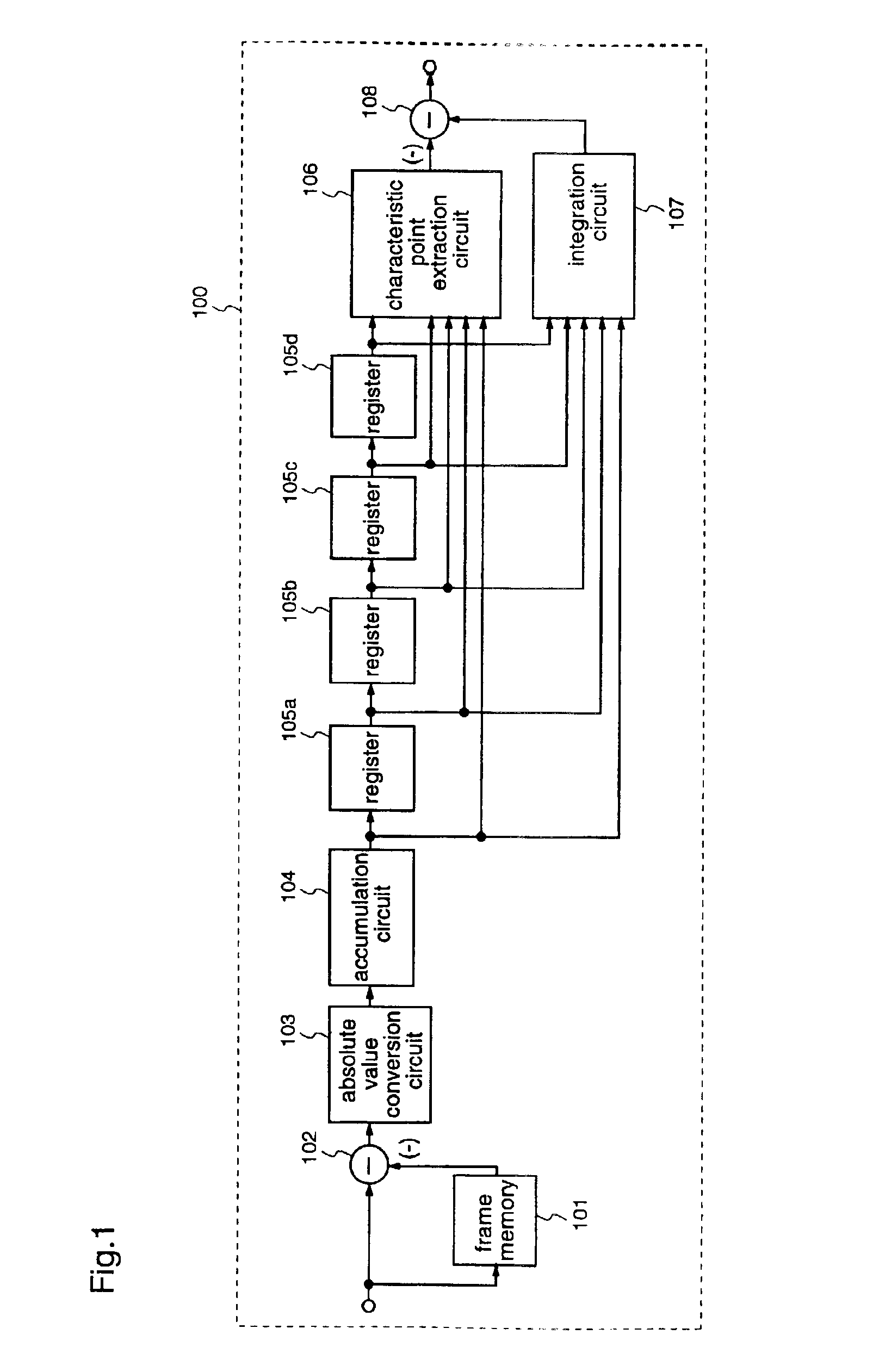
[0017]FIG. 1 is a block diagram illustrating an image motion detecting circuit 100 according to a first embodiment of the present invention. The image motion detecting circuit 100 includes a frame memory 101 for delaying an inputted image signal by a period corresponding to one frame, a subtracter 102 for calculating a level difference of pixels existing at the same spatial position in the inputted image signal between frames, an absolute value conversion circuit 103 for obtaining the absolute value of the level difference calculated by the subtracter 102 for each pixel, an accumulation circuit 104 which resets an accumulated value to zero at the head of a frame and accumulates the absolute values for each frame to obtain an accumulated value, N registers 105 (N is a natural number that is equal to or larger than 4) for holding accumulated values of N pieces of inter-frame difference absolute values for each frame, and a characteristic point extraction circuit 106 for ...

embodiment 2

[Embodiment 2]

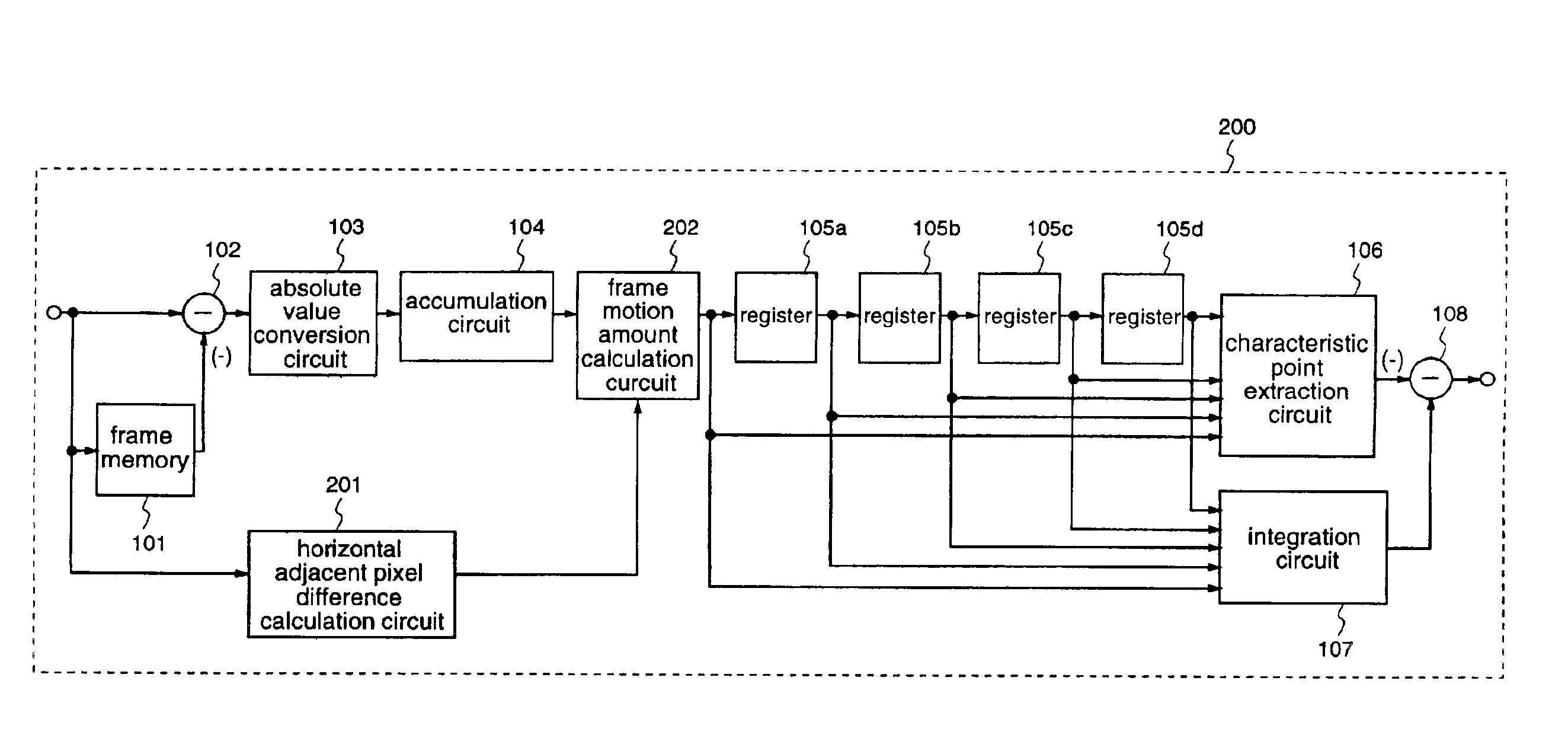
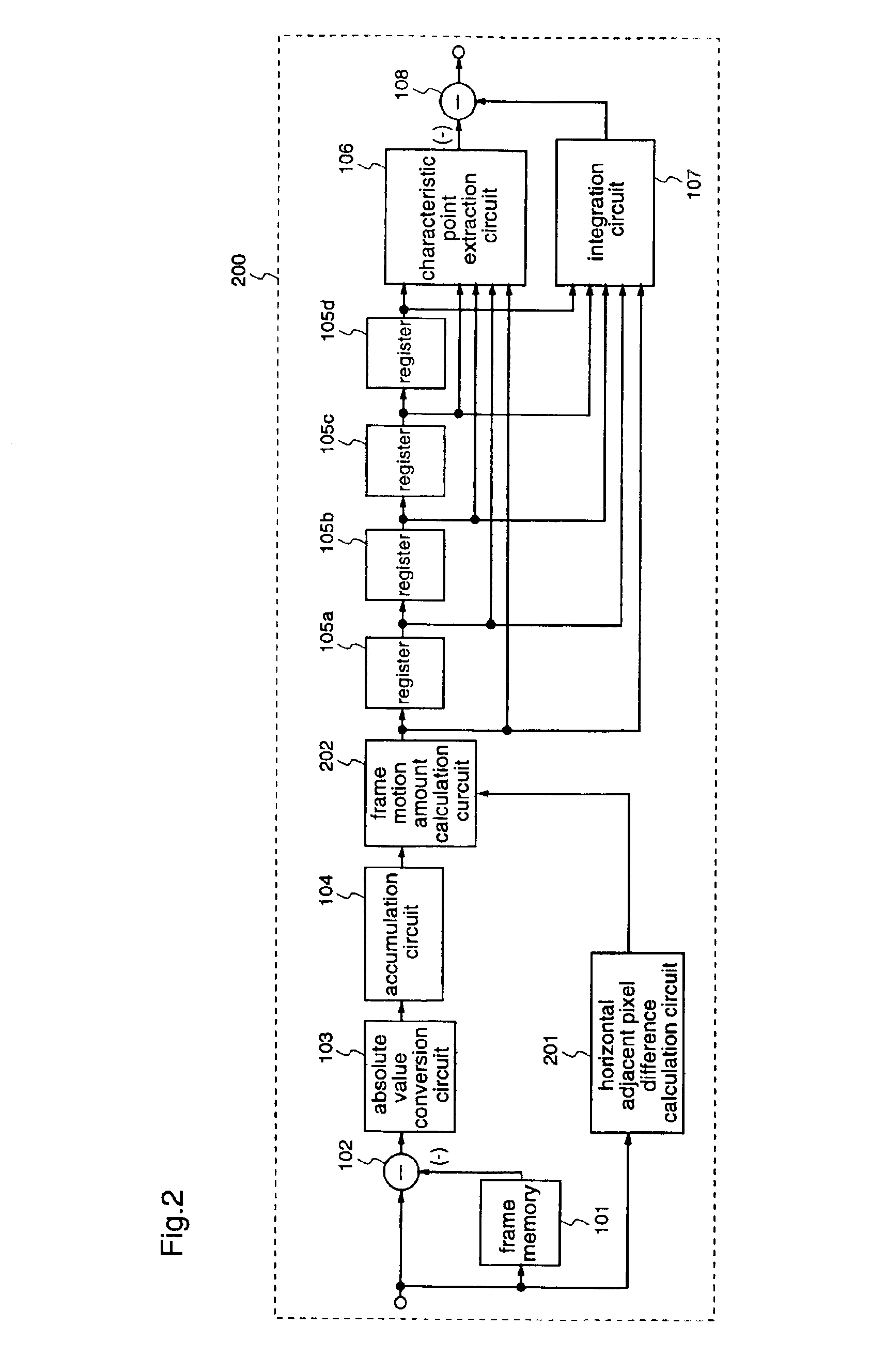
[0029]FIG. 2 is a block diagram illustrating a structure of an image motion detecting circuit 200 according to a second embodiment of the present invention. The same elements in the image motion detecting circuit 100 as shown FIG. 1 are given the same reference numerals, and their descriptions are omitted here. In this second embodiment, like in the first embodiment, the image motion detecting circuit 200 is provided with four registers 105 (registers 105a to 105d), and detects a motion amount during a period corresponding to 6 frames.

[0030]The image motion detecting circuit 200 according to the second embodiment is different from the image motion detecting circuit 100 in that the detecting circuit 200 includes, as shown in FIG. 2, a horizontal adjacent pixel difference calculation circuit 201 and a frame motion amount calculation circuit 202. The horizontal adjacent pixel difference calculation circuit 201 accumulates horizontal adjacent pixel differences of an input ...


PUM


Abstract

An image motion detecting circuit and an image motion detecting method of the present invention can accurately detect motion of such an image sequence that different still pictures are connected with each other. Inter-frame difference absolute values of an inputted image signal during a predetermined frame period are held by plural registers 105. Then, the maximum value is extracted from the inter-frame difference absolute values which are held by the plural registers 105, and the extracted maximum value is subtracted from the sum of the inter-frame difference absolute values during the predetermined frame period, thereby detecting the motion of the whole image sequence.

Description

FIELD OF THE INVENTION[0001]The present invention relates to an image motion detecting circuit and an image motion detecting method for detecting an amount of motion corresponding to a whole image sequence of a television signal or the like.BACKGROUND OF THE INVENTION[0002]As an example of a prior art relating to a circuit for detecting motion of a television signal or the like, a motion detecting circuit described in Japanese Patent No. 2585544 is known. FIG. 4 is a block diagram illustrating a structure of the motion detecting circuit that is disclosed in this literature. This motion detecting circuit includes, as shown in FIG. 4, an input terminal 401, a frame memory 402, a subtracter 403, a motion information conversion circuit 404, an integration circuit 405, and an output terminal 406. A television signal that is inputted through the input terminal 401 is inputted to the frame memory 402. The subtracter 403 calculates a difference between input and output of the frame memory 4...

Claims


Application Information

Patent Timeline
Patent Type & Authority Patents(United States)
IPC IPC(8): G06T7/20
CPCG06T7/2053G06T7/254G06T7/20
Inventor SHIBATA, HIDEAKI
Owner PANASONIC CORP
Why Eureka
Try Eureka