

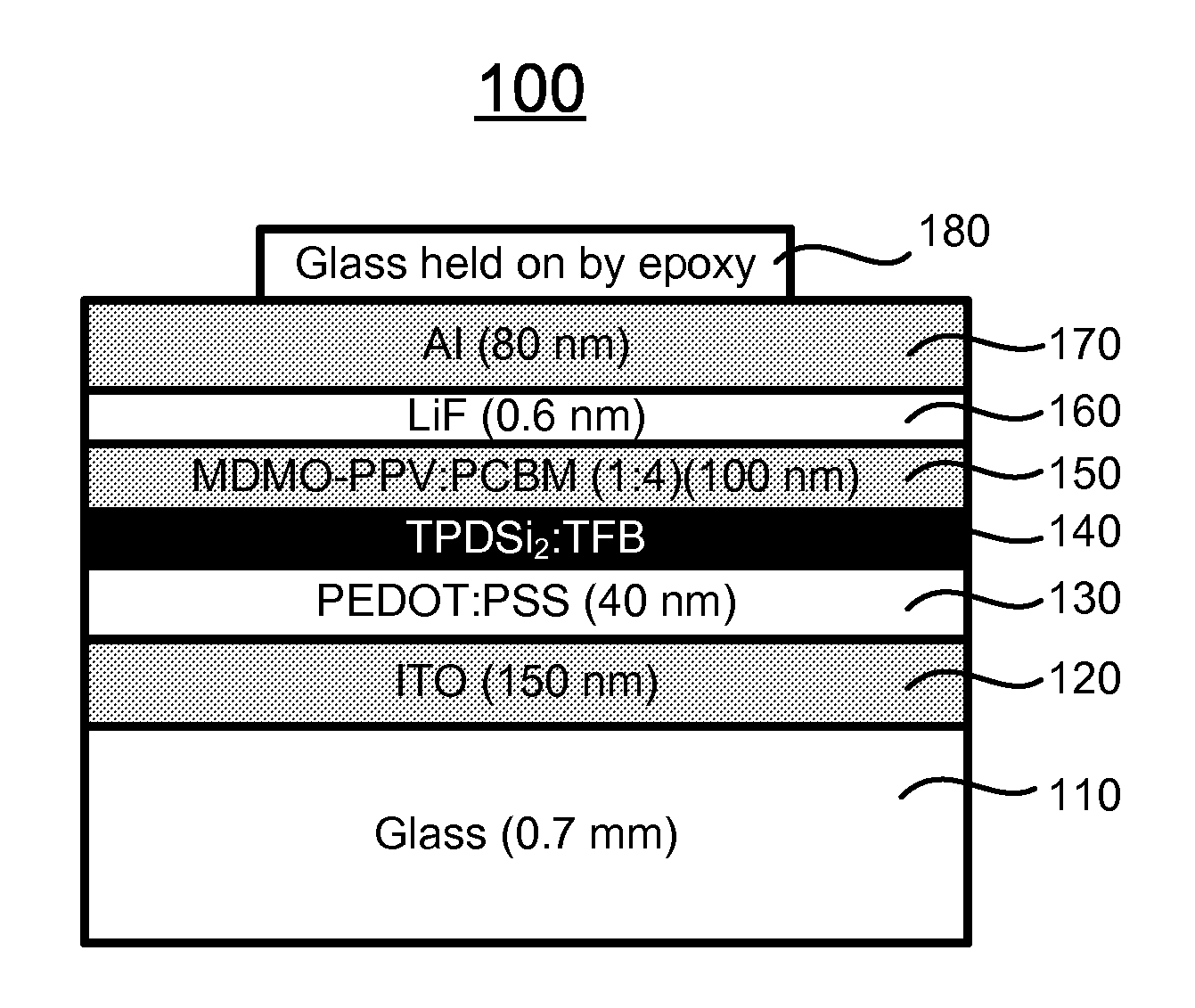
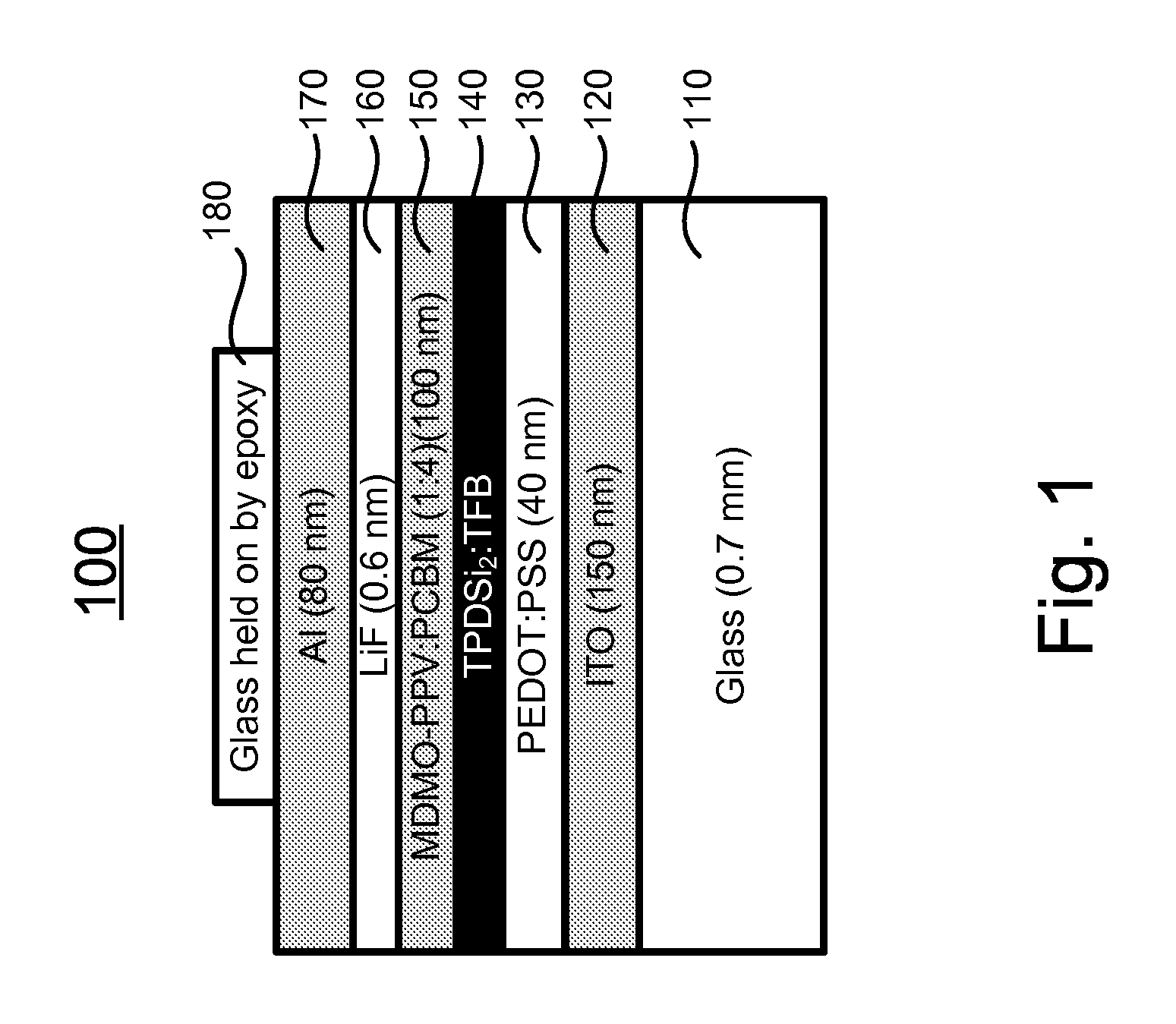
Electron-blocking layer / hole-transport layer for organic photovoltaics and applications of same
a photovoltaic and electron-blocking technology, applied in the field of photovoltaic devices, can solve the problems of limiting the realization of the maximum theoretical open-circuit voltage vsub, the power conversion efficiency of opv cells is currently too low for them to be used commercially, and the unaddressed need in the art, so as to improve the open-circuit voltage voc of bhj solar cells
- Summary
- Abstract
- Description
- Claims
- Application Information
AI Technical Summary
Benefits of technology
Problems solved by technology
Method used
Image

Examples
Embodiment Construction
[0036]The present invention is more particularly described in the following examples that are intended as illustrative only since numerous modifications and variations therein will be apparent to those skilled in the art. Various embodiments of the invention are now described in detail. Referring to the drawings, like numbers indicate like components throughout the views. As used in the description herein and throughout the claims that follow, the meaning of “a”, “an”, and “the” includes plural reference unless the context clearly dictates otherwise. Also, as used in the description herein and throughout the claims that follow, the meaning of “in” includes “in” and “on” unless the context clearly dictates otherwise. Moreover, titles or subtitles may be used in the specification for the convenience of a reader, which shall have no influence on the scope of the present invention. Additionally, some terms used in this specification are more specifically defined below.
Definitions
[0037]T...
PUM
| Property | Measurement | Unit |
|---|---|---|
| thickness | aaaaa | aaaaa |
| thickness | aaaaa | aaaaa |
| temperature | aaaaa | aaaaa |
Abstract
Description
Claims
Application Information