Lighting System with Lighting Dimmer Output Mapping

a technology of lighting dimmer and output mapping, which is applied in the field of mapping the output of lighting dimmer, can solve the problems of increasing intensity and limited ability of dimmers to provide precision control at low measured light levels

Active Publication Date: 2008-09-18
SIGNIFY HLDG BV
View PDF68 Cites 137 Cited by
  • Summary
  • Abstract
  • Description
  • Claims
  • Application Information

AI Technical Summary

Benefits of technology

[0022]In one embodiment of the present invention, a method for mapping dimming output signal values of a lighting dimmer using a predetermined lighting output function and driving a light source in response to mapped digital data includes receiving a dimmer output signal and receiving a clock signal having a clock signal frequency. The method also includes detecting duty cycles of the dimmer output signal based on the clock signal frequency and converting the duty cycles of the dimmer output signal into digital data representing the detected duty cycles, wherein the digital data correlates to dimming levels. The method further includes mapping the digital data to light source control signals using the predetermined lighting output function and operating a light source in accordance with the light source control signals.
[0023]In another embodiment of the present invention a method for mapping dimming output signal values of a lighting dimmer using a predetermined lighting output function and operating a light source in response to mapped dimming output signal values includes receiving a dimmer output signal, wherein values of the dimmer output signal represent duty cycles having a range of approximately 95% to 10%. The method also includes mapping the dimmer output signal values to light source control signals using the predetermined lighting output function, wherein the predetermined lighting output function maps the dimmer output signal values to the light source control signals to provide an intensity range of the light source of greater than 95% to less than 5%. The method further includes operating a light source in accordance with the light source control signals.
[0024]In another embodiment of the present invention, a method for mapping dimming output signal values of a lighting dimmer using a predetermined lighting output function and driving a light source in response to mapped dimmer output signal values includes receiving a dimmer output signal, wherein values of the dimmer output signal represents one of multiple dimming levels. The method also includes applying a signal processing function to alter transition timing from a first light source intensity level to a second light source intensity level and mapping the dimmer output signal values to light source control signals using the predetermined lighting output function. The method further includes operating a light source in accorda...

Problems solved by technology

Thus, increasing current supplied to an LED increases the intensity of the LED, and decreasing current supplied to t...

Method used


Image

  • Lighting System with Lighting Dimmer Output Mapping
  • Lighting System with Lighting Dimmer Output Mapping
  • Lighting System with Lighting Dimmer Output Mapping

Examples


Embodiment Construction

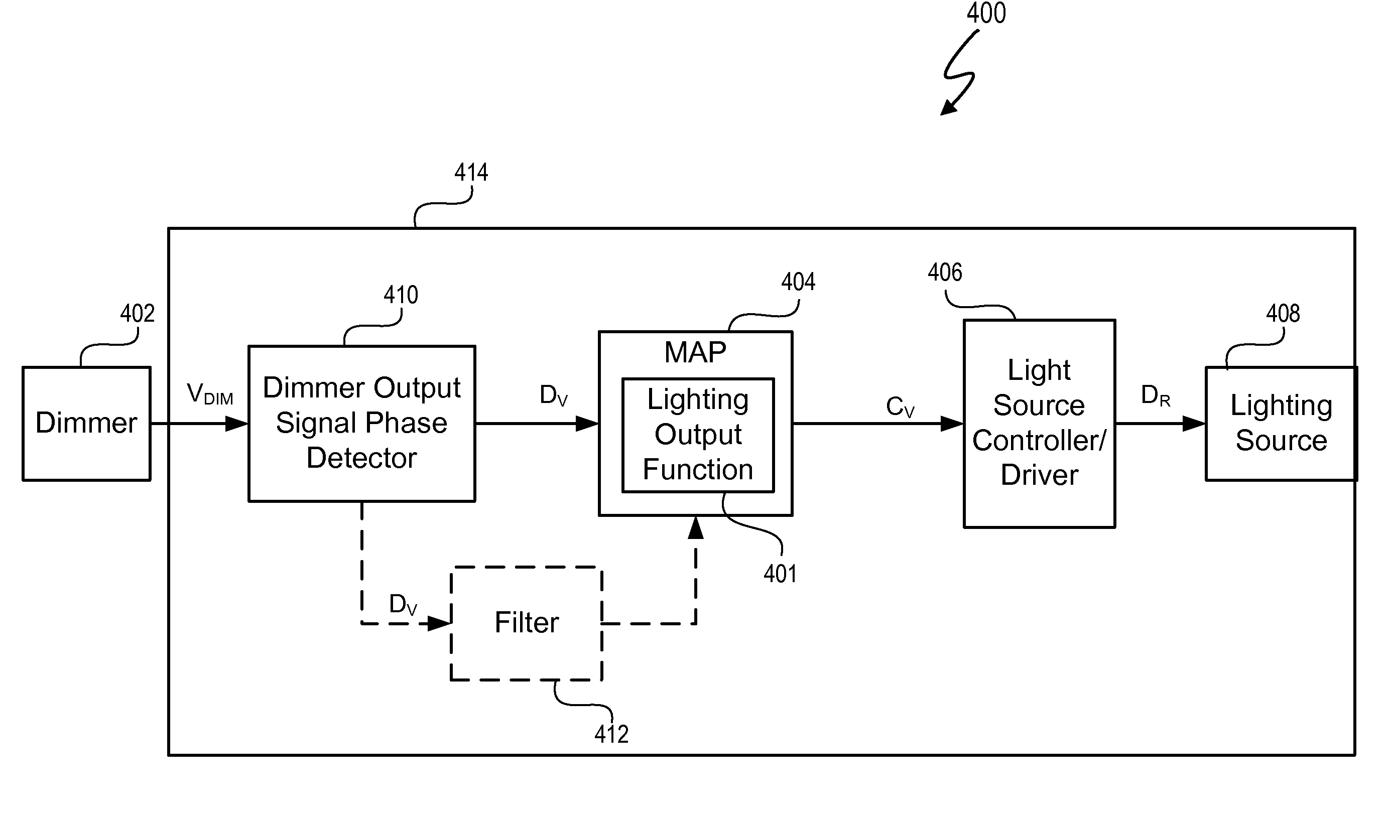
[0039]A system and method map dimming levels of a lighting dimmer to light source control signals using a predetermined lighting output function. In at least one embodiment, the dimmer generates a dimmer output signal value. At any particular period of time, the dimmer output signal value represents one of multiple dimming levels. In at least one embodiment, the lighting output function maps the dimmer output signal values to any lighting output function such as a light level function, a timing function, or any other light source control function. In at least one embodiment, the lighting output function maps the dimmer output signal value to one or more different dimming values that is / are different than the dimming level represented by the dimmer output signal value. In at least one embodiment, the lighting output function converts a dimmer output signal values corresponding to measured light levels to perception based light levels. A light source driver operates a light source in ...


PUM


Abstract

A system and method map dimming levels of a lighting dimmer to light source control signals using a predetermined lighting output function. The dimmer generates a dimmer output signal value. At any particular period of time, the dimmer output signal value represents one of multiple dimming levels. In at least one embodiment, the lighting output function maps the dimmer output signal value to a dimming value different than the dimming level represented by the dimmer output signal value. The lighting output function converts a dimmer output signal values corresponding to measured light levels to perception based light levels. A light source driver operates a light source in accordance with the predetermined lighting output function. The system and method can include a filter to modify at least a set of the dimmer output signal values prior to mapping the dimmer output signal values to a new dimming level.

Description

CROSS-REFERENCE TO RELATED APPLICATION[0001]This application claims the benefit under 35 U.S.C. § 119(e) and 37 C.F.R. § 1.78 of U.S. Provisional Application No. 60 / 894,295, filed Mar. 12, 2007 and entitled “Lighting Fixture”. U.S. Provisional Application No. 60 / 894,295 includes exemplary systems and methods and is incorporated by reference in its entirety.[0002]U.S. Provisional Application entitled “Ballast for Light Emitting Diode Light Sources”, inventor John L. Melanson, Attorney Docket No. 1666-CA-PROV, and filed on Mar. 31, 2007 describes exemplary methods and systems and is incorporated by reference in its entirety.[0003]U.S. patent application entitled “Color Variations in a dimmable Lighting Device with Stable Color Temperature Light Sources”, inventor John L. Melanson, Attorney Docket No. 1667-CA, and filed on Mar. 31, 2007 describes exemplary methods and systems and is incorporated by reference in its entirety.[0004]U.S. Provisional Application entitled “Multi-Function Du...

Claims


Application Information

Patent Timeline
IPC IPC(8): H05B41/39H05B44/00
CPCH05B33/0809H05B37/02H05B33/0848H05B45/14H05B47/10H05B47/165
Inventor MELANSON, JOHN L.PAULOS, JOHN J.
Owner SIGNIFY HLDG BV
Why Eureka
Try Eureka