Magnetic integration structure

a technology of magnetic integration and structure, applied in the field of magnetic parts, can solve the problems of high probability of being destroyed, proportion becomes physically unstable, reliability deterioration, etc., and achieve the effects of reducing the winding space on the side of the series coil, reducing the loss of copper, and reducing the magnetic member of the magnetic par

Inactive Publication Date: 2008-09-18
FUJI ELECTRIC CO LTD +1
View PDF4 Cites 59 Cited by
  • Summary
  • Abstract
  • Description
  • Claims
  • Application Information

AI Technical Summary

Benefits of technology

The invention allows for adjusting the size difference between two parts of an electric device's iron core based on its winding density. This results in less copper loss, reduces the amount of material needed, and makes it possible to create smaller devices at lower costs. It also helps reduce wasted space by eliminating the requirement for narrow windings.

Problems solved by technology

The technical problem addressed in this patent is to create a small-sized and low-cost integrated solution for a DC-DC converter by integrating a transformer and coils as a single part, while also reducing the likelihood of damage and improving reliability. Additionally, the patent aims to address the issue of uneven winding density and increased winding resistance and copper loss in the winding process.

Method used


Image

  • Magnetic integration structure
  • Magnetic integration structure
  • Magnetic integration structure

Examples


Embodiment Construction

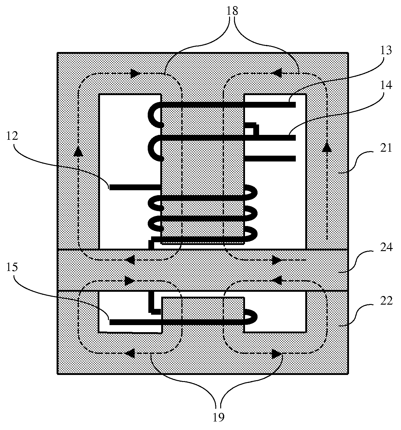
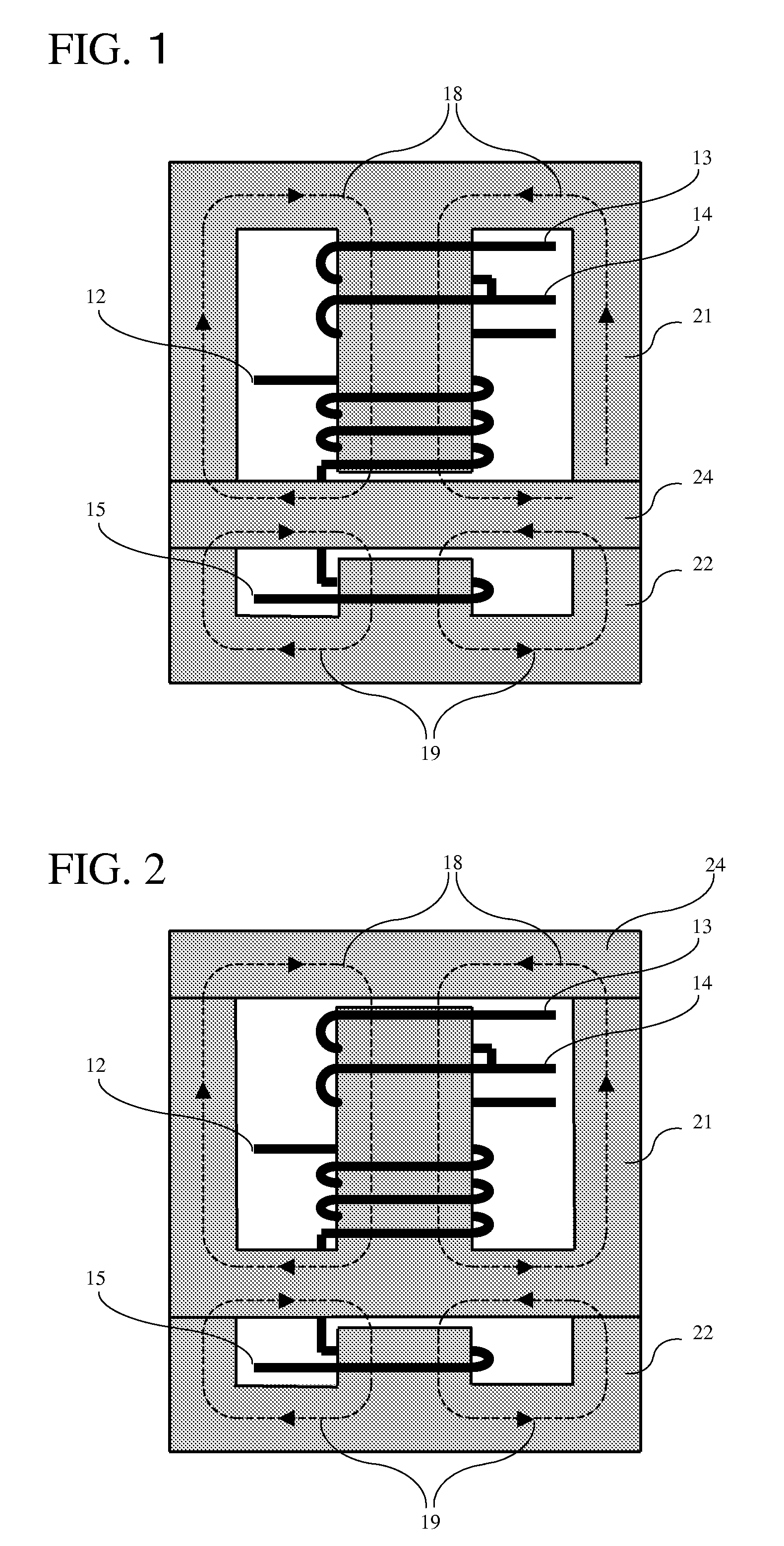
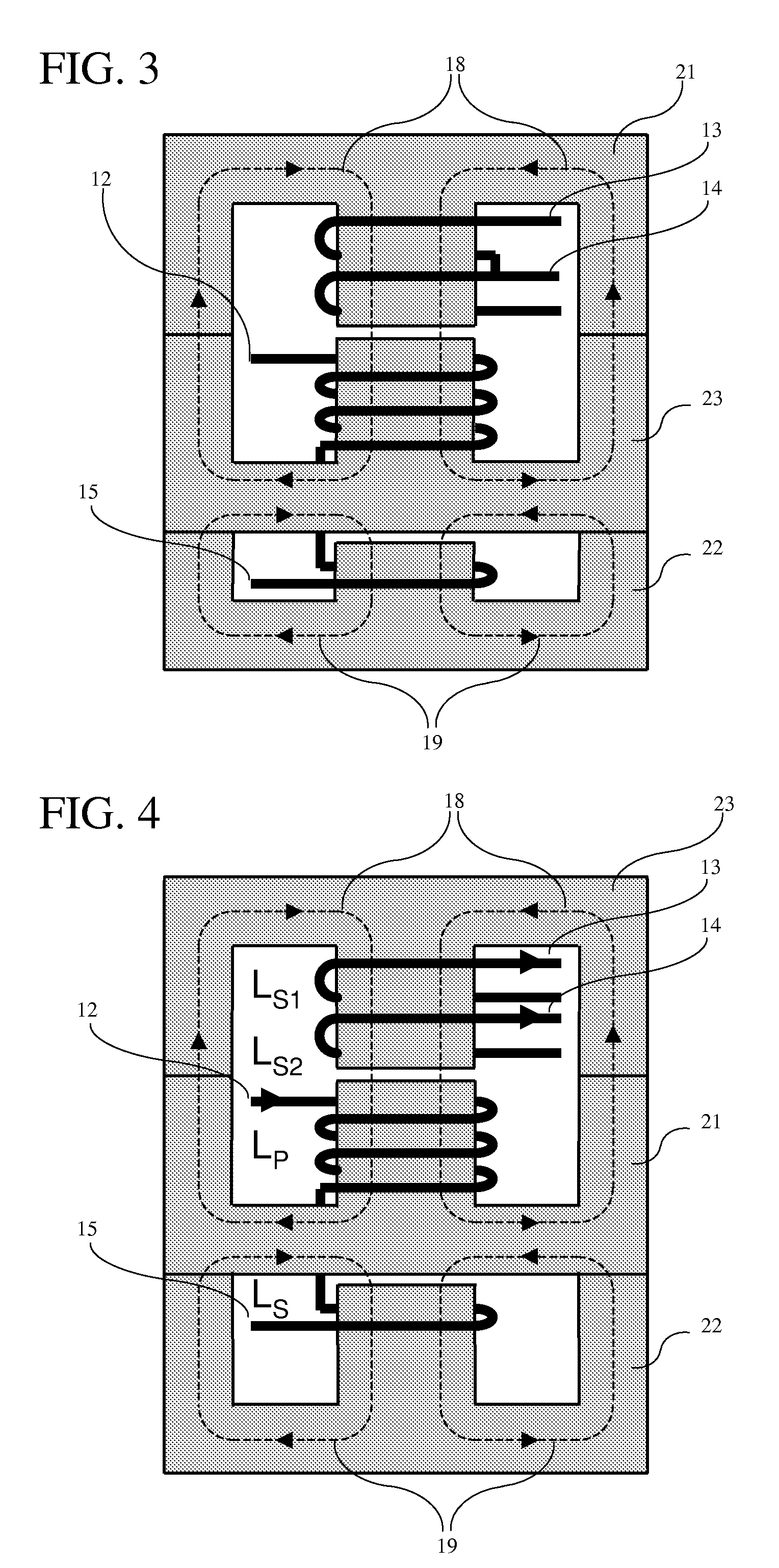
[0023]A winding space on a side of a transformer needing a large winding space is increased and a winding space on a side of a series coil needing only a small winding space is reduced. Thereby, windings on a side of the transformer can be constituted by a pertinent winding thickness, and copper loss can be reduced. Further, by adjusting the winding space to the necessary winding space, the amount of material of a magnetic member is reduced and a small-sized and low cost formation is achieved.

[0024]FIG. 1 shows one embodiment of the invention. According to this embodiment, similarly to the background art shown in FIG. 7, the core is fixed at two portions of supports on both sides, and therefore, the embodiment is physically solid, strong in response to impact or vibration and the reliability thereof is high. Further, the winding space constituting the winding 15 on a side of the series coil 5 is reduced, and a space constituting the windings 12, 13, 14 of the transformer of the para...


PUM


Abstract

A magnetic part having a first iron core wound with a winding constituting a transformer and an inductance component of a parallel coil and a second iron core wound with an inductance component of a series coil, in which a ratio of the dimensions of the first iron core and the second iron core are in accordance with their respective winding densities.

Description


Claims


Application Information

Patent Timeline
Owner FUJI ELECTRIC CO LTD
Why Eureka
Try Eureka