A Stator Modular Ring Winding Double Rotor Permanent Magnet Motor

A technology of ring winding and permanent magnet motors, which is applied in the shape/style/structure of winding conductors, magnetic circuits, electromechanical devices, etc., and can solve the problems of ineffective use of the space at the end of the motor, increased copper wire consumption, and increased copper consumption of the motor, etc. problems, to simplify the processing and distribution process, facilitate mass production, and improve torque density

Active Publication Date: 2021-10-19
NANJING UNIV OF AERONAUTICS & ASTRONAUTICS
View PDF4 Cites 0 Cited by
  • Summary
  • Abstract
  • Description
  • Claims
  • Application Information

AI Technical Summary

Problems solved by technology

like figure 1 As shown, the traditional 1-pair winding connection method requires the winding coil to have a very long end span, the space at the end of the motor cannot be effectively utilized, and the amount of copper wires is increased, the copper consumption of the motor is relatively increased, resulting in a decrease in motor efficiency

Method used


Image

  • A Stator Modular Ring Winding Double Rotor Permanent Magnet Motor
  • A Stator Modular Ring Winding Double Rotor Permanent Magnet Motor
  • A Stator Modular Ring Winding Double Rotor Permanent Magnet Motor

Examples


Embodiment 1

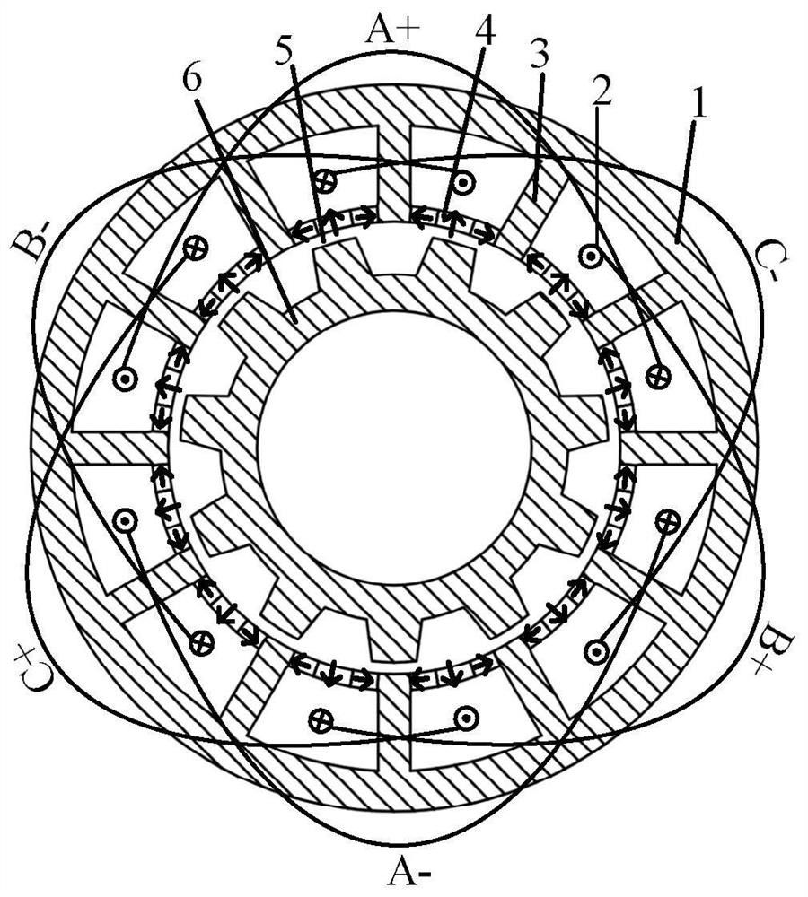
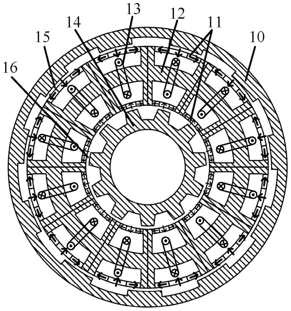
[0030] Such as figure 2 As shown, the structure of Embodiment 1 of the present invention includes an inner rotor 14, an outer rotor 10, and several modular stators 12, and all the modular stators are sequentially spliced ​​according to the circumferential direction to form a complete stator, and the stator is located between the inner rotor 14 and the Between the outer rotor 10, and the inner rotor 14 and the outer rotor 10 respectively form independent air gaps 16 and 15 with the stator. Each modular stator has an inner stator slot and an outer stator slot in the radial direction, the inner stator slot is close to the inner rotor, the outer stator slot is close to the outer rotor, the stator teeth are on both sides of the stator slot, and the space between the inner stator slot and the outer stator slot is It is the stator yoke, and the stator yoke of each modular stator has an armature winding 13 wound in a ring, and permanent magnets 11 are arranged at the slots of the inn...

Embodiment 2

[0040] Such as Figure 9 As shown, the difference between this embodiment and Embodiment 1 lies in the modular stator, since the stator is spliced ​​by discrete modular stators, which affects the reliability of the motor operation. Therefore, in this embodiment, a dovetail slot 31 is provided at the junction of the modularized stators to fix the adjacent stator modules and increase the reliability of the entire motor system. . Other structures of the motor of this embodiment are the same as those of Embodiment 1.


PUM


Abstract

The invention discloses a stator modular annular winding double-rotor permanent magnet motor, which includes an inner rotor, an outer rotor and several modular stators. All the modular stators are sequentially spliced ​​to form a complete stator. between, and the inner rotor and the outer rotor respectively form independent air gaps with the stator; each modular stator has an inner stator slot and an outer stator slot along the radial direction, and the stator teeth are on both sides of the stator slot, and the inner stator slot and the Between the outer stator slots is the stator yoke. The stator yoke of each modular stator has an armature winding wound in a circular manner. There are permanent magnets at the slots of the inner stator slots and outer stator slots. The permanent magnets A pair of stator poles is formed with adjacent stator teeth. The invention overcomes the disadvantages of long end windings, large copper consumption, low end space utilization, low motor torque and power density of the traditional stator permanent magnet permanent magnet motor, and is beneficial to improving the efficiency of the motor.

Description

technical field [0001] The invention belongs to the field of motors, in particular to a permanent magnet motor. Background technique [0002] Due to the use of rare earth permanent magnet materials, permanent magnet motors have the advantages of high torque density, high power density and high efficiency, and are especially suitable for aerospace, wind power generation, electric vehicles and other fields. In recent years, field modulated permanent magnet motors have been extensively studied due to their advantages of high torque density and high efficiency, and are very suitable for low-speed direct drive applications. The stator static magnetic field of the stator permanent magnet field modulation motor is modulated by the rotating salient pole rotor and interacts with the armature magnetic field to realize electromechanical energy conversion. However, the number of pole pairs of the magnetic field modulated by the stator magnetic field and the rotating salient pole rotor i...

Claims


Application Information

Patent Timeline
Patent Type & Authority Patents(China)
IPC IPC(8): H02K16/02H02K1/14H02K1/17H02K3/28
CPCH02K1/145H02K1/17H02K3/28H02K16/02H02K2201/03
Inventor 李烽王凯孙海阳孔金旺张琳张建亚
Owner NANJING UNIV OF AERONAUTICS & ASTRONAUTICS
Why Eureka
Try Eureka