
Method and System For Calculating Depth Information of Object in Image

Inactive Publication Date: 2008-09-18
KOREA ELECTRONICS TECH INST
View PDF2 Cites 7 Cited by
  • Summary
  • Abstract
  • Description
  • Claims
  • Application Information

AI Technical Summary

Benefits of technology

[0009]It is an object of the present invention to provide a method and a system for calculating a depth information of objects in an image wherein an area occupied by two or

Problems solved by technology

However, in accordance with the block-based disparity search method, a search is carried out using a sum of an absolute value of a difference of an entire comparison block without using an accurate optical flow.
The method is disadvantageous in that a value different from an actual movement vector is determined to be the disparity.
Therefore, an accurate disparity cannot be calculated.
On the other hand, when a SIFT (Scale Invariant Feature Transform) method, which is one of most used feature-based search methods, is used, a number of feature points is not sufficient to find the disparity of an entirety of the image.
Therefore, the accurate disparity cannot be detected.

Method used


Image

  • Method and System For Calculating Depth Information of Object in Image
  • Method and System For Calculating Depth Information of Object in Image
  • Method and System For Calculating Depth Information of Object in Image

Examples


Embodiment Construction

[0021]Preferred embodiments of the present invention will now be described in detail with reference to the accompanied drawings. The preferred embodiments of the present invention may vary in their forms, and a scope of the present invention should not be limited to the embodiments described below. The preferred embodiments of the present invention are provided so as to give a complete description of the present invention to a skilled in the art.

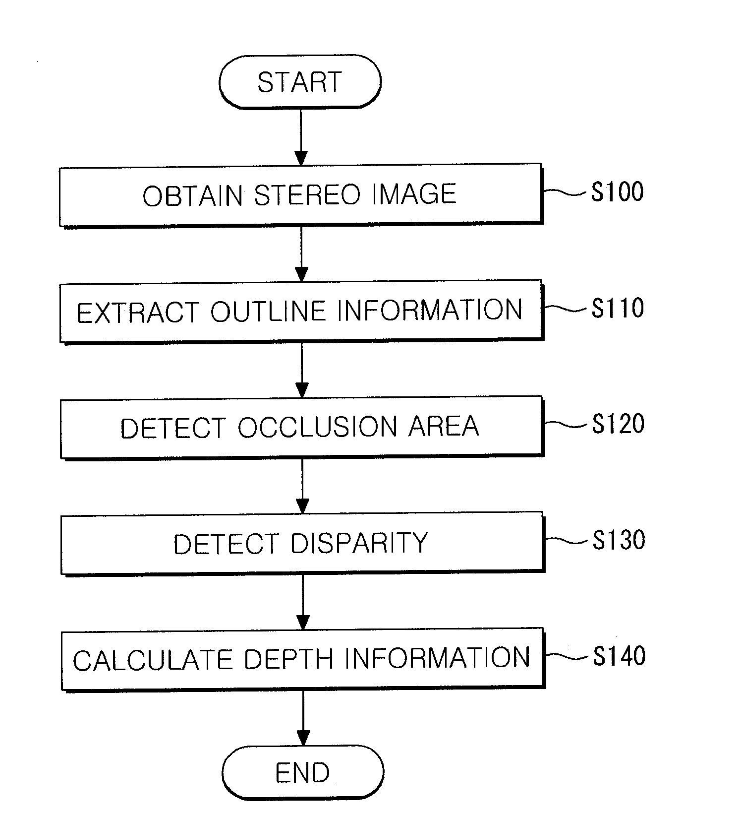
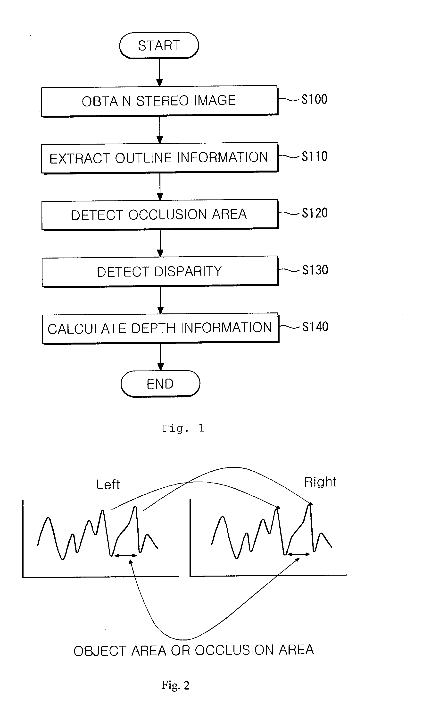
[0022]FIG. 1 is a flow diagram illustrating a method for calculating a depth information of an object in accordance with the present invention.

[0023]Referring to FIG. 1, two or more objects, a first object and a second object for instance, are photographed using a stereo image input means to obtain an image (S100). When the two or more objects are photographed simultaneously, an occlusion area wherein the two or more objects overlap may be generated.

[0024]Thereafter, an outline information of each of the first object and the second object in...


PUM


Abstract

A method and a system for calculating a depth information of objects in an image is disclosed. In accordance with the method and the system, an area occupied by two or more objects in the image is classified into an object area and an occlusion area using an outline information to obtain an accurate depth information of each of the objects.

Description

BACKGROUND OF THE INVENTION[0001]1. Field of the Invention[0002]The present invention relates to a method and a system for calculating a depth information of objects in an image, and in particular to a method and a system for calculating a depth information of objects in an image wherein an area occupied by two or more objects in the image is classified into an object area and an occlusion area using an outline information to obtain an accurate depth information of each of the objects.[0003]2. Description of Prior Art[0004]A stereo camera is special camera for obtaining two images simultaneously. The stereo camera includes two lenses being spaced apart by a predetermined distance for photographing an identical object. A 3-dimensional effect may be achieved when the two images are viewed through a stereoscopic viewer.[0005]A human determines a distance by two eyes. The stereo camera has two lenses of an identical capability having a distance of about 6.5-7 cm since a distance between...

Claims


Application Information

Patent Timeline
IPC IPC(8): G06K9/00G06V10/10G06V10/98
CPCG06K9/03G06K9/20G06T2207/10012G06T7/0075G06K2209/40G06T7/593G06V10/98G06V10/10G06V2201/12G06T7/40G06T7/00
Inventor CHOI, BYEONGHOSONG, HYOKBAE, JINWOO
Owner KOREA ELECTRONICS TECH INST
Learn More